
 English
 usheenthermal

5 Best Practices for AI Accelerator Server Thermal Design
Date:2026-09-20
AI accelerator server thermal design gets dicey fast: one weak interface, stubborn hotspot, or mismatched coolant can throttle expensive compute. For buyers, thermal materials aren’t side details—they’re performance decisions with real consequences.
Smart sourcing means looking past flashy conductivity numbers. These five practices connect interfaces, cooling hardware, insulation, structural materials, and real-world validation.
Quick Answers for AI Accelerator Server Thermal Design
→ Inspect thermal interfaces: verify liquid metal wetting, PCM conformity, grease coverage, graphene pad contact, and gap filler condition.
→ Choose materials wisely: match PCM transition specs, embed copper vapor chambers, use high‐conductivity epoxies, and integrate dielectric fluids where needed.
→ Manage airflow: balance intake/exhaust, deploy direct‐touch heat pipes, prevent recirculation with baffles, and monitor with thermocouples.
→ Validate with data: benchmark air vs. liquid cooling gains, assess quick‐disconnect coupling reliability, and optimize manifold distribution for even coolant flow.

This image was generated with the assistance of AI; it is not a real photograph and is for reference only.
5 Signs Your AI Accelerator Server Is Overheating
Heat trouble rarely starts with smoke or a shutdown. In AI accelerator server thermal design, smaller clues usually appear earlier, from drifting GPU temperatures to clock cuts. Catching them early can keep accelerator thermal management from becoming a costly headache.
Rising GPU Junction Temperatures Despite Liquid Metal Alloy
Watch the temperature trend.
- A rising GPU junction temperature despite liquid metal alloy can point to a pump-out effect or interface degradation.
- Check mounting pressure and die clearance. High thermal conductivity cannot fix weak physical contact.
For AI accelerator server thermal design, compare like-for-like workloads rather than one peak reading.
Erratic Readings at Phase Change Material Interfaces
Check behavior around the transition point.
- If a sensor reading tracks the transition point under steady load, the film is operating outside its intended window.
- Repeated jumps suggest poor interface contact or rising contact resistance, not normal behavior.
AI accelerator cooling should settle into a repeatable pattern after warm-up.
Visible Gaps in Thermal Conductive Silicone Grease Layers
Cracked or missing silicone grease is a pretty clear red flag in AI accelerator server thermal design.
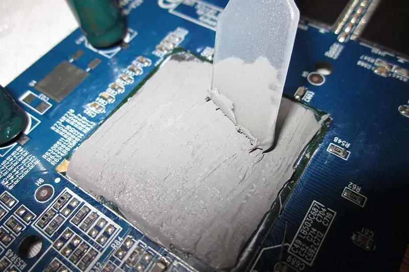
Inspect for a thermal gap, void formation, or micro-void.
- Check the dispersion layer for uneven coverage.
- Look for squeeze-out around die edges.
- Rising thermal resistance means heat has a harder trip to the heatsink.
Sheen Technology thermal-interface solutions can be evaluated against the required pressure, coverage, and service temperature.
Sharp Thermal Spikes Near a Graphene Thermal Pad
Utilizing a vertically aligned structure—as opposed to lateral heat diffusion—the graphene thermal sheet accelerates heat transfer efficiency along the thickness direction.
| Check | Normal | Warning | Critical |
| GPU junction | <80°C | 80–90°C | >90°C |
| Spike rise | <3°C/s | 3–6°C/s | >6°C/s |
| Pad compression | 20–30% | 10–20% | <10% |
| Hot-spot delta | <10°C | 10–20°C | >20°C |
| Fan duty | <70% | 70–90% | >90% |
Treat these as screening ranges, not universal hardware limits. A thermal spike, hot spot, poor compression rate, or edge delamination deserves inspection.
Performance Throttling from Worn Thermal Conductive Gap Filler
Confirm the symptom.
- Performance throttling cuts clocks as component temperatures reach protection limits.
Inspect the interface.
- A thermal gap filler can suffer material degradation and permanent compression set.
Match the replacement.
- Verify hardness and load deflection so pressure remains safe while thermal dissipation improves.
Good AI accelerator server thermal design connects those thermal signs with clock telemetry, helping distinguish a worn interface from airflow or coolant problems.
AI Accelerator Server Thermal Design Essentials
Effective AI accelerator server thermal design starts at the chip and extends through spreading, cooling, insulation, and bonding. Sheen Technology combines these thermal design choices so accelerator servers can handle dense loads without making cooling hardware overly complicated.
Optimizing Phase-Change Material for High Heat Flux
PCM absorbs bursts through latent heat, giving high-power chips extra time before temperatures spike.
Match the melting point to the desired device temperature.
- Keep the layer thin enough to limit interface thermal resistance.
- Raise composite thermal conductivity when rapid heat dissipation matters.
Treat PCM as a thermal interface material only after checking contact pressure.
- Microencapsulated PCM can handle repeated cycles with less mess.
- Paraffin composites are handy for short accelerator heat peaks.
For AI accelerator server thermal design, steady-state cooling still carries the long-term load.
Selecting a Copper Vapor Chamber for Uniform Dissipation
A copper vapor chamber works as a low-profile heat spreader, moving concentrated GPU heat across a larger sink area. This two-phase cooling process uses evaporation near the die and condensation elsewhere.
- Check GPU power and orientation.
- Match the evaporator wick to expected heat flux and return flow.
- Compare total thermal resistance, not just chamber thickness.
Sheen Technology can align chamber footprint and wick design with real server thermal limits, which helps avoid costly overbuilding.
Integrating Dielectric Cooling Fluid in Micro-Channel Cold Plates
Getting accelerator cooling right requires balancing flow against pumping power.
Size each micro-channel for useful surface area.
- Model fluid dynamics around bends and manifolds.
- Avoid uneven flow across accelerator zones.
Pair the cold plate with a compatible dielectric fluid.
- Confirm seals, tubing, and materials tolerate long exposure.
- Target a strong heat transfer coefficient without excessive pressure loss.
This form of liquid cooling suits dense accelerator server racks where air cooling runs out of headroom.
Implementing Polyimide Film for Electrical Insulation
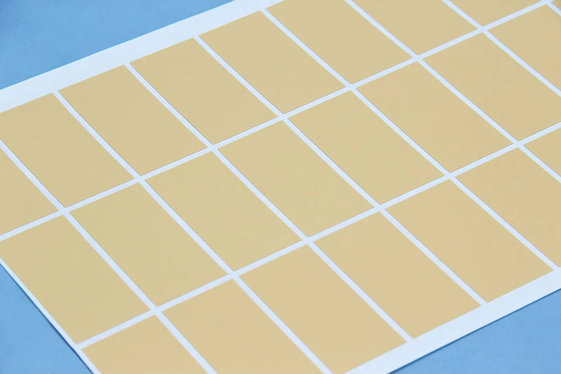
Thin polyimide film can provide electrical insulation while adding little thermal resistance, a useful trade in compact AI server hardware.
- Dielectric strength: Match film thickness to operating voltage.
- Voltage breakdown: Include manufacturing tolerances and edge conditions.
- Thermal stability: Check continuous temperatures and hot spots.
A thin-film layer also needs clean, wrinkle-free contact. For hotter locations, ceramic sheets or mica pads may be a better fit.
Embedding High-Thermal-Conductivity Epoxy for Structural Stability
A conductive epoxy resin can secure parts while creating a secondary thermal path.
Mechanical design
- Use the material as a structural adhesive where vibration matters.
- Verify cured mechanical stability under server handling.
Thermal design
- Select higher thermal conductivity around local hot spots.
- Match thermal expansion to copper, ceramic, and PCB materials.
Used as a potting compound, epoxy also protects fragile connections. In AI accelerator server thermal design, Sheen Technology can balance bonding strength with thermal cycling needs rather than chasing conductivity alone.
Prevent Hot Spots With Targeted Airflow Management
Good AI accelerator server thermal design keeps heat from settling where cooling is weakest. By matching air paths with component heat loads, Sheen Technology can help operators keep accelerator hardware cooler, protect performance, and avoid wasting fan power.
Balancing Intake and Exhaust for Even Air Distribution
Stable airflow distribution starts with a sensible balance between the intake vent and exhaust fan.
Cooling supply
- Match the cfm rating to GPU and accelerator demand.
- Keep the ventilation grille clear enough to limit resistance.
Pressure control
- Check static pressure through crowded server areas.
- Maintain a useful pressure differential so downstream VRMs and memory still receive cool air.
For AI accelerator server thermal design, this balance helps aluminum heatsinks work without cranking fans harder than needed.
Leveraging Direct-Touch Heat Pipes to Channel Hot Air
A heat pipe moves concentrated heat quickly through phase change and high effective thermal conductivity.
At the chip
- A thin thermal interface material improves contact.
- A copper baseplate spreads local heat.
Toward the fins
- Thermal conduction carries energy into the pipe network.
- A vapor chamber can spread wider hot spots before airflow handles final heat dissipation.
That makes AI accelerator server thermal design less prone to heat buildup around nearby accelerator cards.
Avoiding Recirculation Zones with Strategic Baffle Placement
Hot exhaust taking a shortcut back toward an intake is bad news. An air baffle provides airflow guidance, while a chassis partition can stop a stubborn recirculation zone.
Use exhaust diversion near dense cards, but avoid overly tight channels that create turbulent flow and extra fan load. A carefully placed thermal barrier can also separate intake and exhaust paths.
Monitoring Hot Spots with Embedded Thermocouple Arrays
A thermocouple array shows what airflow models may miss.
Measurement points
- Put each temperature sensor near GPUs, memory, VRMs, cold plates, and exhaust routes.
- Good sensor placement reveals the true temperature gradient.
Operational checks
- Use real-time monitoring and thermal telemetry during representative AI loads.
- Keep data logging active to spot recurring heat patterns.
This closes the loop in AI accelerator server thermal design, letting airflow changes follow measured hot spots rather than guesswork.
Real-World Data: 30% Lower Temps With Liquid
Real-world gains depend on workload, coolant setup, and room conditions. For AI accelerator server thermal design, controlled testing shows where liquid cooling can cut component temperatures while keeping service and pumping needs practical.
Comparing Dielectric Cooling Fluid to Air in AI Servers
A fair comparison keeps accelerator load and ambient temperature equal; otherwise, a claimed 30% temperature reduction may look better than it really is.
Cooling path
- Air cooling moves heat through sinks and room air.
- Fan speed can rise sharply under dense AI accelerator loads, increasing noise and power use.
Dielectric fluid handles heat much closer to hot chips.
- Its effective heat dissipation approach supports high-density AI server thermal design, including immersed servers.
- Fluid properties such as thermal conductivity still need checking against operating temperature and material compatibility.
| What to hold constant | What to measure | Why it matters |
| Accelerator load profile | Junction and case temperatures | Hot spots, not averages, set throttling |
| Ambient / supply temperature | Pump power and fan power | The energy side of the comparison, often omitted |
| Workload duration and repetition | Coolant flow and ΔT | Verifies the loop is delivering the assumed flow |
| Coolant chemistry and concentration | Branch-level pressure drop | Catches one accelerator hogging flow while another runs hot |
Measured pump and fan energy should also enter the comparison. That keeps energy efficiency claims grounded rather than, well, just looking good on a temperature chart.
Impact of Quick-Disconnect Couplings on Maintenance Downtime
Quick-disconnect couplings can make AI accelerator server thermal design much easier to service. A technician can isolate a cold plate without draining a whole coolant loop.
During replacement, a built-in valve mechanism closes as the connection separates, limiting fluid leakage.
After reconnection:
- Check seals and pressure.
- Confirm coolant flow.
- Test several connection cycles before approving the hardware.
Faster serviceability can reduce maintenance downtime, while validated seals support system reliability and operational continuity.
Boosting Flow with Manifold Distribution Pipe Efficiency
Good manifold distribution prevents one accelerator from hogging coolant while another runs hot.
Set branch dimensions for the required flow rate.
- Lower hydraulic resistance helps maintain useful coolant flow.
- Avoid oversized restrictions at fittings and hose transitions.
Measure branch-level pressure drop, not merely pump outlet pressure.
- Balanced paths improve pipe efficiency and keep accelerator cooling more consistent.
- Compatible EPDM hoses and couplings simplify maintenance without sacrificing flow.
For practical AI thermal design, stable distribution matters as much as raw pump capacity. Better balance turns coolant delivery into predictable thermal performance, especially across parallel high-power accelerators.
【Request a Custom Quote】Chasing hot spots across dense accelerator trays? Send us your accelerator power map, interface stack-up and bond-line dimensions, target junction temperatures, cooling architecture (air, cold plate, or immersion), and airflow layout, and our engineers can recommend a material set for AI accelerator server thermal design that keeps throttling and fan power in check.
Sheen Thermal
Dongguan Sheen Electronic Technology Co., Ltd · Founded in 2008
Manufacturer of thermal interface materials and silicone foam for automotive electronics, energy storage, power electronics, communications and consumer electronics.
Certified
- ISO 9001:2015
- ISO 14001:2015
- IATF 16949:2016
What we supply
- Thermal conductivity Up to 90 W/m·K
- Thickness 0.3–10.0 mm
- Custom & samples Die-cut to drawing, 3–7 days
LAST:Nothing