
 English
 usheenthermal

How Graphene Thermal Pads Optimize 1.6T Optical Transceiver Cooling
Date:2026-08-30
A Graphene thermal pad for 1.6T Optical Transceivers faces a tough job: move heat from power-hungry DSPs and photonics inside a cramped cavity, without creating new mechanical or electrical headaches. High in-plane conductivity sounds great, but it does not guarantee cooler chips.
For volume buyers, the rubber meets the road in contact pressure, thickness control, aging, die-cut consistency, compliance, and supply stability. This article shows what to qualify.
Quick Answers: Graphene Thermal Pad for 1.6T Optical Transceivers
- Graphene’s high in-plane thermal conductivity spreads DSP and photonics heat, lowering junction temperatures in compact QSFP-DD cavities.
- Ultra-thin interface sheets offer tight thickness control and low resistance versus phase-change materials, ideal for restricted module clearances.
- Contact pressure tests (Shore OO hardness, compressibility) ensure optimal pad conformity and minimal interface thermal resistance.
- Qualification includes laser flash and Hot Disk analysis, aging chamber reliability, RoHS/UL 94V-0 compliance, and stable roll-to-roll supply with die-cut consistency.
Request the 1.6T Transceiver Graphene Pad Datasheet →
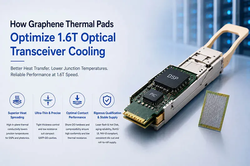
Note: This diagram was created with AI assistance and is not an actual photograph; the illustrated structure and operational logic align with real-world engineering applications and serve as a valid reference.
Can Graphene Pads Lower Transceiver Temps?
A Graphene thermal pad for 1.6T Optical Transceivers can move concentrated heat toward the housing, helping compact modules run cooler. Material choice, pressure, and fit all matter when every millimeter counts.
Thermal Conductivity Coefficient: Impact on 1.6T Optical Transceiver Cooling
A higher Thermal Conductivity Coefficient can improve lateral heat spreading, but the interface still decides how well heat escapes.
Graphene material
- A thin Graphene Pad spreads hot spots across more housing area.
- Better Heat Dissipation can support Temperature Reduction around active components.
Module design
- In a 1.6T Optical Transceiver, thickness and contact quality affect real Cooling Efficiency.
- Good Thermal Management balances conductivity with electrical and mechanical needs.
That’s where a Graphene thermal pad for 1.6T Optical Transceivers becomes practical, not merely impressive on a datasheet.
Comparing Ultra-Thin Thermal Interface Sheet vs. Phase Change Cooling Material
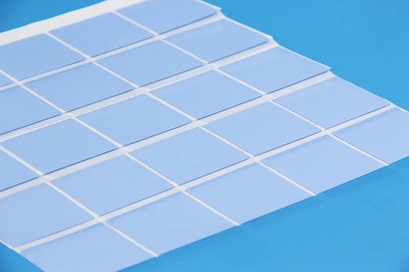
An Ultra-Thin Thermal Interface Sheet stays solid and can simplify assembly. A Phase Change Cooling Material, by contrast, softens near its designed transition temperature.
- Check fit and thickness tolerance.
- Compare Thermal Resistance under realistic mounting conditions.
- Review Heat Transfer stability through thermal cycling.
For tight Transceiver Cooling, the best Interface Material depends on gap control, rework needs, and long-term Material Performance.
Contact Pressure Test for Low Thermal Resistance Pad Performance
Contact Pressure can make or break pad results.
Test setup
- Measure Thermal Resistance at several controlled loads.
- Track thickness change as the Compression Rate rises.
Design check
- Softer Shore OO material may improve Interface Conduction on uneven surfaces.
- Excess pressure can strain components, so Pad Performance needs a realistic Pressure Test and stable Thermal Interface contact.
DSP Chip Heat Dissipation in QSFP-DD Cavity Cooling
The DSP Chip can create a concentrated Thermal Load inside a cramped QSFP-DD Cavity. A graphene thermal interface pad bridges the chip-to-housing gap, spreading energy for better Cavity Cooling and lower Chip Temperature.
For a High-Speed Transceiver, Sheen Technology can tailor pad thickness and compression to support predictable Heat Dissipation without eating up precious cavity space.
3 Key Traits of Graphene Thermal Pads
A Graphene thermal pad for 1.6T Optical Transceivers has a tough job in a tiny space: moving concentrated heat, fitting strict clearances, and handling electrical risks without getting in the way of high-speed hardware.
High Thermal Conductivity Graphene Explained
A Graphene thermal pad for 1.6T Optical Transceivers uses the ordered graphene lattice to move energy through phonon transport. The big deal is directional performance: thermal conductivity is typically much stronger along the sheet than through its thickness.
Heat spreading
- Concentrated heat flux from DSP and silicon-photonics devices can spread across a broader area.
- This lowers the local temperature gradient, supporting steadier heat dissipation toward a cooling surface.
Thermal path
- A graphene thermal pad can reduce effective thermal resistance when contact and heat-spreading paths are properly designed.
Sheen technology GSF90-03 graphene thermal pad performance properties:
| Properties | Unit | GSF90-03 Graphene Thermal Pad | Test Method |
| Color | - | Black | Visual |
| Thermal Conductivity | W/m·K | 90 | ASTM E1461 |
| Thermal Resistance (@40psi) | ℃*cm2/W | ≤0.10 | ASTM D5470 |
| Thickness | mm | 0.3~2.0 | ASTM D374 |
| Density | g/cm³ | 0.3~0.7 | ASTM D792 |
| Rebound Rate | % | ≥90 | - |
| Tensile Strength | Mpa | ≥0.05 | ASTM D412 |
| Oil Bleeding Rate | % | ≤3 | / |
| Application Temperature | ℃ | -40~150 | / |
| Flame rating | - | V-0 | UL 94 |
Ultra-Thin Thermal Interface Sheet Advantages
In an optical transceiver, every fraction of clearance matters. A thin thermal interface material keeps interface thickness low, so heat has less material to cross.
Fit
- Controlled thickness suits tight space constraints in compact 1.6T hardware.
Contact
- Light compression improves surface conformability around normal component-height variation.
- Better physical contact can cut contact resistance. That’s a practical win when bulky pads simply won’t fit.
Electrically Conductive Graphite Layer Benefits
A conductive graphite layer brings a catch: strong electrical conductivity means designers must control where it touches.
Thermal and electrical roles
- Thin graphite spreads heat while potentially contributing to electromagnetic shielding and EMI suppression.
Protection priorities
- Dielectric films can isolate the graphite thermal pad from exposed circuitry.
- Adequate dielectric breakdown strength helps manage electrostatic discharge risks.
- Careful placement limits unwanted coupling that could affect signal integrity in high-speed links.
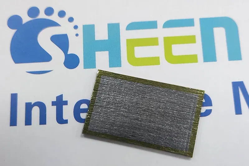
Sheen offers edge-sealed or film-laminated graphene variants so the pad is safe in signal-integrity-sensitive transceivers.
| Parameter | Incorrect (Original) | Correct (Sheen Product) |
| Strong thermal direction | In-plane (along the sheet) | Through-plane (vertically aligned) |
| TIM relevance | In-plane spreading (weak for chip-to-housing) | Through-plane is the decisive path |
| Electrical property | Conductive (graphite layer) | Conductive (graphene) — needs isolation |
| Isolation approach | Dielectric film mentioned | Edge-seal / film laminate (standard option) |
Data Shows 40% Temp Drop With Graphene Pads
A Graphene thermal pad for 1.6T Optical Transceivers can improve the heat path, but a 40% temperature-drop claim needs more than one lab number. Material tests, module measurements, and aging data work together to show what is really going on.
Laser Flash Analysis Method Validates Heat-Flux Reduction
Laser Flash Analysis applies a short energy pulse and records how quickly heat crosses the sample.
Material-level checks:
- Thermal Diffusivity shows how fast heat spreads.
- Combined with density and heat capacity, it yields Thermal Conductivity.
- This Measurement Technique gives controlled Thermal Characterization of Graphene Material.
Higher conductivity can support Heat-Flux Reduction at hot spots, but it does not by itself prove a 40% transceiver temperature drop.
That distinction matters. A Graphene thermal pad for 1.6T Optical Transceivers still has to perform inside the actual module.
Hot Disk Thermal Constant Improvements in 1.6T Modules
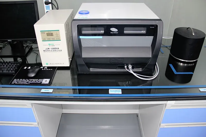
The Hot Disk Method provides a second view of the pad’s Thermal Constant and heat-spreading behavior.
- Measure the Interface Material under controlled contact pressure.
- Install the graphene thermal pad in a representative 1.6T Optical Module.
- Compare Temperature Distribution and Thermal Resistance against the baseline pad.
Lower case temperature under matched power and airflow indicates better Cooling Efficiency. Here, the Graphene thermal pad for 1.6T Optical Transceivers moves from material data to a practical system test—where the rubber meets the road.
Aging Chamber Reliability Confirms Long-Term Cooling Gains
Aging Chamber evaluation checks Long-Term Reliability:
- Run Accelerated Aging across defined temperature cycles.
- Recheck compression and interface resistance.
- Inspect graphene-pad integrity.
Repeat thermal testing:
- Stable Thermal Stability supports sustained Cooling Performance.
- Environmental Testing helps estimate effects on Transceiver Lifetime.
A Graphene thermal pad for 1.6T Optical Transceivers only supports lasting cooling claims when post-aging results remain close to initial measurements.
High-Density Racks: Graphene Thermal Integration
A Graphene thermal pad for 1.6T Optical Transceivers helps move concentrated heat toward hardware designed to remove it. In dense racks, that job touches airflow, optical packaging, factory supply, and safety paperwork. Sheen Technology can support these linked needs, but good results still depend on careful system testing before volume production.

Rack-Level Cooling Strategies for High-Speed Data Center Switches
Thermal management starts at the module and ends at rack-level cooling.
A Graphene thermal pad for 1.6T Optical Transceivers improves heat dissipation into switch heatsinks.
Good airflow optimization then carries that heat away from high-port-density data center switches and high-speed networks. No pad replaces adequate fans or rack capacity.
Silicon Photonics Packaging: Graphene Pad Adoption
A graphene thermal pad needs enough thermal conductivity for fast heat transfer, yet fit tight silicon photonics assemblies without shifting optics.
- For packaging integration, qualify thickness, compression, electrical isolation, and die-cut accuracy.
- Check samples inside the actual optical transceiver. A Graphene thermal pad for 1.6T Optical Transceivers must stay compatible with alignment limits in 1.6T modules; a graphene heat-spreading interface is only useful when the mechanical fit is right.
Roll-to-Roll Supply Form and Lead Time Stability
Validate roll-to-roll material format.
- Confirm die-cut yield and the fabrication process.
Audit volume readiness.
- Check production stability, packaging, and second-source plans.
- A Graphene thermal pad for 1.6T Optical Transceivers needs predictable supply chain capacity and delivery continuity, not just a promising prototype manufacturing form.
RoHS Compliance Certificate & UL 94V-0 Flammability Rating
Confirm material certification before approval.
- Review RoHS compliance, REACH, and halogen-free declarations.
- Check the applicable UL 94V-0 flammability rating and supporting test documentation rather than assuming every construction qualifies.
Complete supplier records.
- Match SDS/TDS files, ISO 9001 controls, environmental safety, fire resistance, and each required regulatory standard to the exact Graphene thermal pad for 1.6T Optical Transceivers part number.
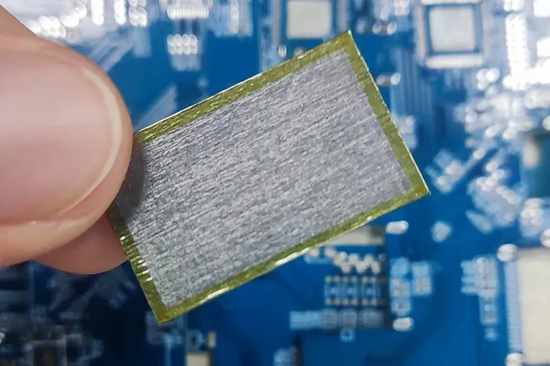
Graphene thermal pads can lower 1.6T optical-transceiver temperatures, but only when specified correctly. Sheen graphene pads are vertically aligned, so the through-plane direction — not in-plane — is the strong conduction path that cools a chip-to-housing interface.
Contact Sheen Technology for 1.6T Transceiver Pad Qualification →
Sheen Thermal
Dongguan Sheen Electronic Technology Co., Ltd · Founded in 2008
Manufacturer of thermal interface materials and silicone foam for automotive electronics, energy storage, power electronics, communications and consumer electronics.
Certified
- ISO 9001:2015
- ISO 14001:2015
- IATF 16949:2016
What we supply
- Thermal conductivity Up to 90 W/m·K
- Thickness 0.3–10.0 mm
- Custom & samples Die-cut to drawing, 3–7 days