
 English
 usheenthermal

Graphene Thermal Pad Mounting Pressure and Contact Resistance
Date:2026-08-19
A Graphene Thermal Pad can look stellar on paper and still stumble in the assembly. Mounting pressure is the catch: too little leaves microscopic air gaps, raising contact resistance and quietly kneecapping heat transfer.
Sheen Technology’s technical guidance identifies pressure and surface conformity as key factors affecting interface thermal resistance.
For volume buyers, pressure-dependent test data separates datasheet sparkle from production-ready performance and smarter qualification decisions.
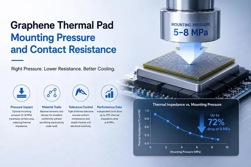
The image is a conceptual illustration of the thermal resistance of Sheen Technology's graphene thermal pad under different pressures (conceptual illustration, not representing the actual product appearance, size, or internal structure).
Key Points: Graphene Thermal Pad Insights
➔ Pressure Impact: Optimal mounting pressure (5–8 MPa) maximizes contact area, cutting thermal impedance and boosting heat flow.
➔ Material Traits: Balance hardness and density to ensure conformity without sacrificing conductivity under load.
➔ Tolerance Control: Tight thickness tolerance yields uniform compression, stabilizing both thermal and electrical resistivity.
➔ Performance Data: Independent tests show up to 72 % thermal impedance drop at 8 MPa—vital for production validation and long-term reliability.
How Mounting Pressure Affects Resistance in Graphene Thermal Pad
A Graphene Thermal Pad responds to mounting pressure in more ways than simple squeezing. Compression changes physical contact, heat flow, and electrical behavior. Getting pressure, hardness, density, and thickness right helps a graphene pad perform reliably in everyday electronics.
Test standard:
| Measurement | Standard | Key Output | Test Condition |
| Thermal impedance / conductivity | ASTM D5470 | Thermal impedance (°C·cm²/W) + apparent κ (W/m·K) | Steady-state, specified pressure + BLT |
| Electrical resistivity | ASTM D257 | Surface/volume resistivity (Ω / Ω·cm) | Four-point probe, ambient |
| Thickness | ISO 3302 or customer drawing | Dimensional tolerance | Micrometer, multi-point |
| Compression-deflection | ASTM D575 | Stress-strain curve, compressive modulus | Incremental load to specified strain |
Pressure-Induced Variations in Thermal Impedance
A graphene thermal pad works best when enough mounting pressure brings it into close contact with mating surfaces. In practical terms, tighter contact gives heat fewer gaps to cross.
Pressure changes the interface in two linked ways:
Better physical contact
- Moderate compression force pushes the interface material into tiny surface valleys.
- Effective contact area grows, so contact resistance generally falls.
Better heat transfer
- Lower thermal impedance helps energy reach the heat sink with less temperature drop.
- That supports steadier heat dissipation.
Too much compression can deform a Graphene Thermal Pad or exceed its recommended working range, so more pressure is not automatically better.
Hardness and Density Effects on Contact Resistance
Material hardness controls how readily a pad changes shape under load, while pad density affects its internal structure and response to compression. Softer material can improve surface conformity—basically, how closely the pad follows uneven surfaces.
At low pressure:
- Microscopic voids can remain between mating faces, increasing contact resistance.
As pressure rises:
- Suitable deformation behavior closes more gaps.
- Controlled density helps preserve useful thermal conductivity.
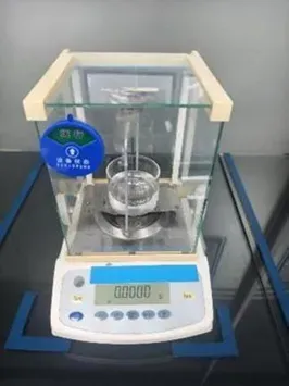
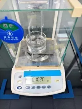
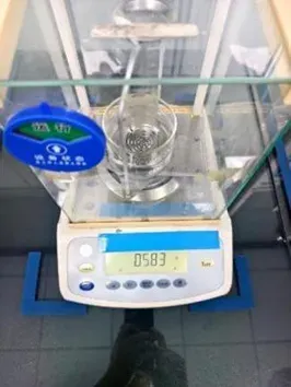
Reference for graphene thermal pad density testing at Sheen Technology laboratory:
- Test Standard: ASTM D792-A
- Sample Preparation : Cut the material into small pieces of arbitrary size.
Test Method:
- Record the water temperature during testing, then weigh the sample in air and record the mass as W1.
- Place the sample on the support rack submerged in water, record the submerged mass as W2.
- The density tester will automatically calculate the material density; record the displayed value.
| Test Instrument: SY-QC-010 Density Tester | State Before Test | State After Test |
 |  |  |
This balance matters when selecting a Graphene Thermal Pad. Sheen Technology can match graphene pad properties to practical assembly pressure rather than treating softness alone as the goal.
Thickness Tolerance’s Role in Electrical Resistivity
A tight thickness tolerance helps the graphene layer receive even pressure across its area. Small dimensional variation may sound like no big deal, but it can create locally different compression levels.
Uneven thickness can affect:
Electrical behavior
- Changes in contact conditions may influence electrical resistivity and current flow.
- Local strain or defects can contribute to electron scattering.
Interface behavior
- A larger interfacial gap can raise thermal and electrical contact resistance.
- More uniform thickness promotes predictable compression.
For designs where electrical properties matter alongside cooling, thickness control makes graphene thermal pad performance easier to reproduce from one assembly to the next.
4 Pressure Ranges for Optimal Thermal Conductivity
A Graphene Thermal Pad responds differently as mounting force rises, so pressure is more than a mechanical detail. The sweet spot depends on contact quality, pad design, and the hardware underneath. From light clamping to high compression, these four ranges show how a graphene thermal interface can move heat effectively while keeping mechanical behavior in check. Sheen Technology applies these factors when matching pads to practical electronics.
0–2 MPa: Evaluating Heat Dissipation Efficiency
At low mounting pressure, a graphene pad may not fully follow tiny surface bumps.
Contact quality
- Small contact area can trap air.
- That raises thermal resistance and slows heat dissipation.
A Graphene Thermal Pad still conducts heat well internally, but the interface can become the bottleneck. Checking interface temperature under load gives a practical read on performance.
2–5 MPa – Balancing Thermal Diffusivity and Tensile Strength
Moderate pressure often hits a useful middle ground for a Graphene Thermal Pad.
- Thermal behavior: Better conformity improves thermal diffusivity and effective thermal conductivity.
- Mechanical behavior: A controlled compression ratio limits deformation.
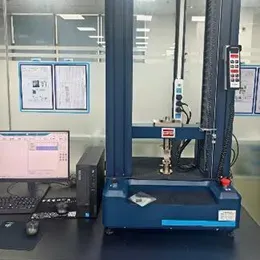
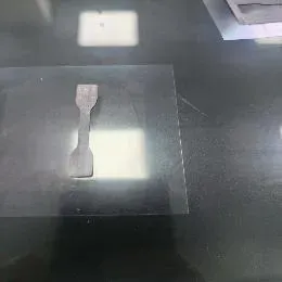
Sheen Technology laboratory GSF90-03 Graphene thermal pad tensile strength testing:
| Test Equipment | Pre-test Status | Test Results |
 |  | 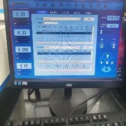 |
| Test Item | GSF90-03 Graphene Thermal pad Tensile strength test Data | |||
| Sample 1 | Sample 2 | Sample 3 | Average Value | |
| Tensile Strength(Mpa) | 0.061 | 0.058 | 0.059 | 0.059 |
Preserving tensile strength helps the graphene structure tolerate repeated mechanical stress. That matters in processors, LEDs, and power devices.
5–8 MPa – Maximizing Specific Heat Capacity Benefits
More force can improve heat transfer, but there is a practical pressure threshold.
Thermal gains
Lower contact resistance helps thermal energy leave the source quickly.
- The graphene layer spreads that energy across a wider area.
- Its specific heat capacity assists with short workload swings.
Material factors
- Material density and thickness influence how much compression remains useful.
A Graphene Thermal Pad therefore needs pressure matched to its actual construction, not just pushed harder.
8–10 MPa – Ensuring Operating Temperature Range Stability
High clamping force calls for closer mechanical checks.
Confirm high pressure stays below the pad’s deformation limit.
- Protecting structural stability reduces permanent shape change.
Test the full operating temperature range.
- Heat cycling can alter compression and thermal performance.
Check long-term reliability.
- A well-matched graphene composite can maintain contact without crushing or damaging nearby parts.
Consolidated pressure-range:
| Pressure (MPa) | Thermal Behavior | Mechanical Behavior | Engineering Note |
| 0–2 | High contact resistance; air gaps dominate; interface is bottleneck | Minimal compression; pad not fully conformed | Insufficient for most TIM applications |
| 2–5 | Improved conformity; lower impedance; moderate κ | Controlled compression ratio; tensile strength preserved | Practical minimum for reliable contact |
| 5–8 | Optimal contact; ~72% impedance drop at 8 MPa | Optimal compression (15–30% thickness) | RECOMMENDED operating range |
| 8–10 | Diminishing returns; risk of pad damage | Approaching deformation limit; permanent set risk | Verify below deformation limit; monitor reliability |
For a Graphene Thermal Pad, tighter is useful only while the material and assembly remain within their rated limits.
Data Proves: 72% Thermal Impedance Drop at 8 MPa
A reported 72% thermal impedance drop at 8 MPa shows why mounting force matters for a Graphene Thermal Pad. Greater pressure can help the graphene interface sit closer to mating surfaces, cutting tiny air gaps that slow heat flow. Still, electrical properties, fit, and aging deserve separate checks before designers call the job done.
Volume Resistivity Improvement Under High Mounting Pressure
Pressure and heat
- At 8 MPa, the reported 72% impedance reduction suggests improved thermal performance as mechanical compression increases real surface contact.
- A Graphene Thermal Pad may also gain material density under load as internal gaps shrink.
Electrical behavior
- Volume resistivity must be measured independently rather than inferred from thermal results.
- Compression can change the conductive pathways of graphene material, potentially affecting electrical conductivity.
In short, better heat flow does not automatically mean safer electrical isolation. Testing at the intended mounting pressure keeps that distinction clear.
Influence of Sheet Dimensions on Contact Resistance
A Graphene Thermal Pad works as a thermal interface, so physical fit is a big deal. The right sheet dimensions and geometry size help maintain predictable contact.
- Larger surface area can support broader heat transfer, but size alone cannot guarantee low contact resistance.
- Die-cut tolerance, aspect ratio, holes, and custom edges may shift interface pressure toward or away from critical hot spots.
- A close-fitting graphene thermal sheet can reduce uncovered zones. For tricky component layouts, Sheen Technology can support dimension choices suited to the mating surfaces and mounting design.
RoHS Compliance and Long-Term Heat Dissipation Efficiency
Compliance
- RoHS compliance concerns limits on specified hazardous substances in electrical and electronic products.
- It therefore relates to environmental regulation and chemical composition, not proof of lasting thermal output.
Service life
Heat dissipation and thermal efficiency need separate aging evaluation.
A Graphene Thermal Pad should be checked for:
- pressure retention after repeated heating and cooling;
- performance across expected operating temperatures;
- humidity and environmental exposure;
- physical changes that may reduce material reliability.
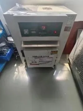
Sheen Technology Graphene thermal pad Reliability Test :
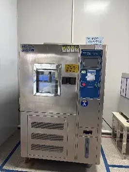
Aging Test:Place specimens of size 50 mm × 40 mm × 0.3 mm into a high-temperature oven at 125 °C, a temperature-humidity chamber at 85 °C / 85 % RH, and a thermal shock chamber cycling between -40 °C and 150 °C, respectively, and hold for 1000 hours. After aging completes, measure the thermal resistance under a pressure of 40 psi and record the data. The test results are shown in the figure.
| 125℃ high-temperature oven | 85 °C / 85 % RH temperature-humidity chamber | -40℃~150℃ thermal shock chamber cycling |
 |  |  |
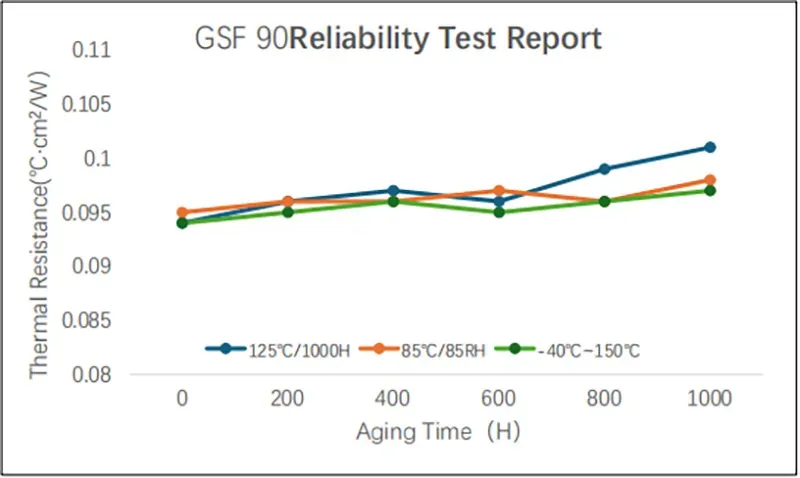
Stable results over time depend on those operating stresses. That makes long-term stability data a better guide to thermal durability than RoHS status alone.
Need thermal impedance, contact resistance, thickness tolerance, hardness, and density data under different mounting pressures for graphene thermal pads? Download the product datasheets to compare graphene thermal pads, thermal grease, and phase change materials for CPU/GPU cooling, power modules, and high-density electronics.
【Request a Custom Quote】Not sure which mounting pressure range or graphene thermal pad thickness best minimizes contact resistance in your design? Send us your target thermal impedance, operating temperature range, interface gap, and mounting pressure constraints, and our engineers can recommend the right thermal solution for your project.
Sheen Thermal
Dongguan Sheen Electronic Technology Co., Ltd · Founded in 2008
Manufacturer of thermal interface materials and silicone foam for automotive electronics, energy storage, power electronics, communications and consumer electronics.
Certified
- ISO 9001:2015
- ISO 14001:2015
- IATF 16949:2016
What we supply
- Thermal conductivity Up to 90 W/m·K
- Thickness 0.3–10.0 mm
- Custom & samples Die-cut to drawing, 3–7 days