
 English
 usheenthermal

From Chip Testing to High-Speed Optical Modules: How Carbon Fiber Thermal Pads Handle Different Cooling Demands
Date:2026-10-27
Sheen’s take on carbon fiber thermal pad selection and application: when you’re facing high-power devices, a pad’s value should be judged by post-assembly temperatures and contact stability — not by a datasheet number alone. We recommend putting thermal capability, compression load, and recovery requirements on the same selection table before deciding what to sample.
Numbers like 20, 30, and 45 W/(m·K) tend to be the first thing procurement and R&D compare. Fair enough — but in a real device, the space between heatsink and component also comes with height tolerances, surface contact realities, and load limits. However impressive a thermal parameter looks, it still has to match those structural conditions.
That’s why we spotlight CSF20-HR, CSF30-HC, and CSF45 — each opens a different door into evaluation:
- Interfaces that must recover after compression and release → start with CSF20-HR.
- Structures that need to absorb gap tolerances → focus on CSF30-HC.
- Projects where mechanical conditions are already defined and heat transfer still needs optimizing → add CSF45 to the test list.
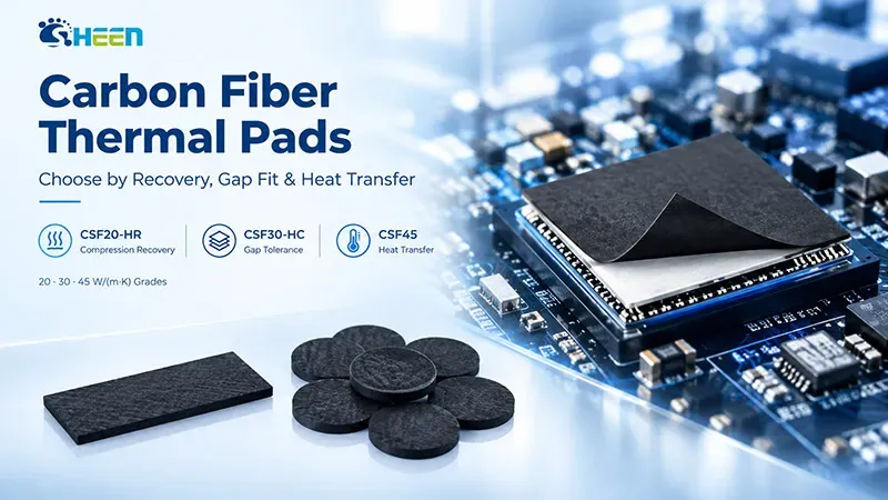
Figure 1. Carbon fiber pad in contact with a device — from Sheen product technical documentation.
All three earn their spot on a sample list for different reasons. Pin down the interface bottleneck first — it makes every later test more targeted, and makes it much easier to tell whether a high-conductivity material actually did anything.
Key Parameters and Test Conditions for the Three Grades
All parameters below come from Sheen’s latest datasheets. Thermal resistance keeps its original units and test conditions. Where a value isn’t listed, we don’t extrapolate — in particular, recovery rate and max compressibility cannot be borrowed across grades.
| Parameter | CSF20-HR | CSF30-HC | CSF45 | Method / Note |
| Thermal conductivity W/(m·K) | 20 | 30 | 45 ± 4.5 | ASTM D5470 |
| Additional conductivity W/(m·K) | 30 | Not listed | Not listed | ASTM E1461 |
| Thermal resistance °C·in²/W | ≤0.33 | 0.10 ± 0.02 | 0.07 ± 0.02 | ASTM D5470 |
| Resistance test condition | 2.0 mm, 30 psi | 1 mm, 10–15% compression | 1 mm, 10–15% compression | Per source datasheet |
| Operating temperature °C | −40 to 150 | −40 to 150 | −40 to 150 | Method not specified |
| Hardness, Shore 00 | 45–55 | 50–60 | 60–70 | ASTM D2240 |
| Recovery rate % | ≥80 | Not listed | Not listed | Method not specified |
| Max compressibility % | Not listed | 30 | Not listed | Method not specified |
| Tensile strength psi | ≥10 | 10 | 10 | ASTM D412 |
| Elongation % | ≥200 | Not listed | Not listed | ASTM D412 |
| Available thickness mm | 0.8–12.0 | 0.3–12.0 | 0.3–12.0 | ASTM D374 |
| Density g/cm³ | 2.1 ± 0.2 | 2.2 (tolerance TBD) | 2.2 ± 0.2 | ASTM D792 |
| Color | Black | Black | Black | Visual |
| Flame rating | V-0 | V-0 | V-0 | UL94 |
| Storage | ≤30 °C, humidity ≤75% | ≤30 °C, humidity ≤75% | ≤30 °C, humidity ≤75% | Cool, shaded place |
| Shelf life | 12 months | 12 months | 12 months | Per datasheet |
*CSF30-HC’s density was printed as “2.2±02” in the source. This table keeps the center value 2.2 and flags the tolerance as to-be-confirmed.
CSF20-HR: A Clear Evaluation Path for Repeatedly Compressed Interfaces
In chip testing, thermal module testing, and other scenarios involving repeated compression and release, conforming on first assembly is only the starting line. After being held, unloaded, and compressed again, can the material recover enough contact to hold up thermally? That’s the question that decides everything downstream.
CSF20-HR brings 20 W/(m·K) conductivity (ASTM D5470), ≥80% recovery, and Shore 00 45–55 hardness. For projects that need heat transfer and shape recovery, that combination is a solid reason to request samples. One caveat: recovery rate does not translate directly into a number of reuse cycles.
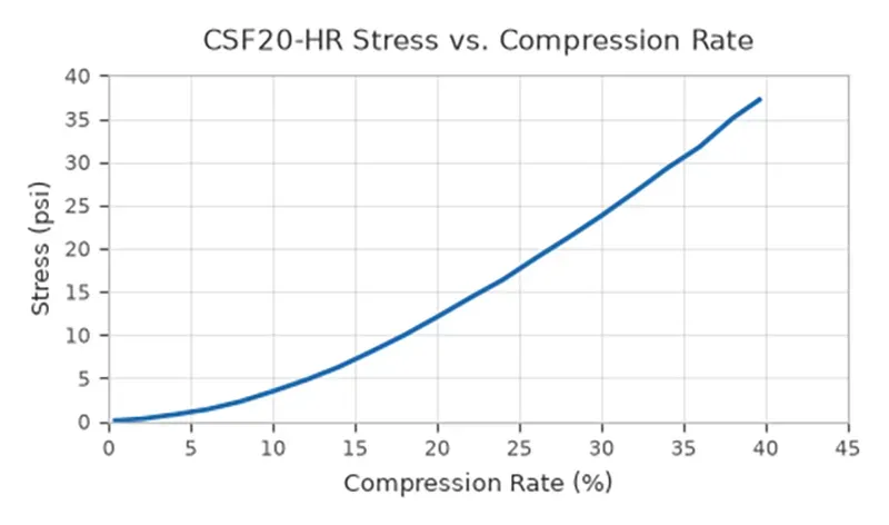
Figure 2 — CSF20-HR stress vs. compression rate curve.
This curve explains why compression must always be designed together with load. The horizontal axis is compression rate; the vertical axis is stress in psi. As compression increases, the required stress climbs — and not proportionally. So “the material is soft” is never a substitute for a device load calculation. Also note: the curve extends to roughly 40% compression, but the displayed range is neither the maximum allowable nor the recommended assembly compression. Once you’ve chosen a thickness, confirm the matching test conditions and raw data with our engineers.
Load calculation example: assume a uniform contact pressure of 20 psi over an effective area of 20 mm × 20 mm — the total load is about 55 N. This example only shows that pressure and area together determine total load; it is not a recommended assembly pressure for CSF20-HR.
Validation suggestion: fix the actual thickness and target compression, record thickness recovery after loading and unloading, then run compression cycles as your project requires and re-measure temperature or resistance. Log the compression ratio, hold time, and post-unload measurement timing of the recovery test together with the results — orphaned numbers help nobody.
CSF30-HC and CSF45: Choose by the Structural Bottleneck
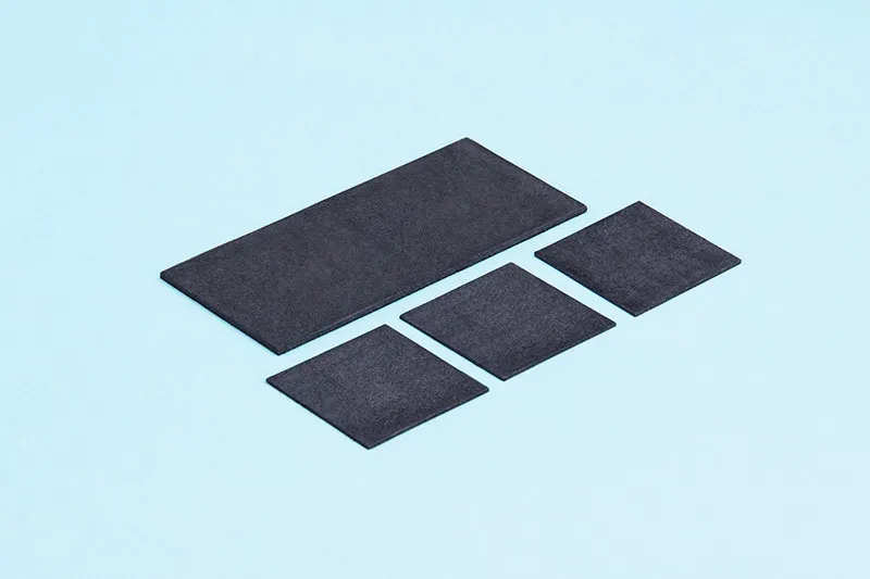
Figure 3. Sheen Technology Carbon fiber Thermal pad overview.
CSF30-HC answers a specific selection question: can high conductivity coexist with assembly compression needs? It uses oriented fiber alignment technology, delivers 30 W/(m·K), lists 30% max compressibility, and covers 0.3–12.0 mm thickness. When one heatsink spans multiple components, height differences and tolerances can leave one spot under-compressed and another overloaded. CSF30-HC belongs on the sample list for exactly these structures — but “it compresses 30%” doesn’t answer “how much force does that take?” Before designing, get the pressure-vs-compression curve for your chosen thickness and check it against device and PCB load limits.
Thickness example: 1.0 mm initial thickness meeting a 0.8 mm assembly gap gives a geometric compression of 20%. That math only describes dimensions — whether the material reaches that state within the allowable load still needs verification. And the max compressibility should never become the default design value for every project.
CSF45 comes in once mechanical conditions are defined, to quantify what higher conductivity buys you. It offers 45 ± 4.5 W/(m·K) with Shore 00 60–70 hardness; at 1 mm under 10–15% compression, thermal resistance is 0.07 ± 0.02 °C·in²/W. For optical modules, chip testing, and other interfaces with demanding heat-transfer requirements, CSF45 is a candidate worth measuring for real. Because its hardness range sits above the other two, don’t reuse your existing assembly compression without rechecking the load — and don’t predict a fixed temperature drop from conductivity alone.
| Thermal Resistance Reading | CSF30-HC | CSF45 |
| Datasheet resistance °C·in²/W | 0.10 ± 0.02 | 0.07 ± 0.02 |
| Stated thickness & compression | 1 mm, 10–15% compression | 1 mm, 10–15% compression |
| Expanded range | 0.08–0.12 | 0.05–0.09 |
Of course, this table alone can’t promise CSF45 delivers a fixed improvement under every assembly condition. Engineering judgment still belongs to controlled testing at the same thickness, same load, same contact conditions. Our selection principle at Sheen: satisfy assembly and contact requirements first, then compare system temperatures. Heat has to cross the material bulk and both contact interfaces — high conductivity only pays off when contact is real.
Match the Grade to the Application
| Application / Requirement | Grade to Evaluate First | Test Focus |
| Chip & thermal module testing — repeated compression | CSF20-HR | Thickness recovery; post-cycle thermal performance; contact state after unloading |
| Multiple components sharing one heatsink — gap & height tolerances | CSF30-HC | Compression at both tolerance extremes; device load & contact uniformity |
| Optical module or RRU interfaces — structure mostly fixed | CSF30-HC or CSF45 | Temperature at actual thickness & load; assembly and electrical boundaries |
| 51.2T / 102.4T switches — specific component interfaces | Screen by structural needs | Test against device power & gap; device class is no substitute for material validation |
Chip testing, thermal module testing, optical modules, and 5G RRU are application directions listed in the datasheets; switches come from promotional materials. Nothing in this table means a specific platform has already been validated.
Request Samples the Smart Way
When you reach out, have these ready:
- Heat dissipation power
- Effective contact area
- Gap and tolerances
- Allowable load
- Operating temperature
- Any repeated assembly/disassembly or insulation requirements
We recommend using your current material as the baseline: fix the heatsink, environment, power, and temperature probe locations, then compare how the new sample performs after assembly. Sheen’s carbon fiber CSF series deserves a place on your validation list precisely because the three grades offer different performance combinations — CSF20-HR for recovery needs, CSF30-HC for conductivity plus compression adaptability, CSF45 for a higher-conductivity option.
【Request a Custom Quote】Hand your test conditions to our engineers together with the product parameters, and every sample request gets closer to a real project decision. Bring your actual structure, and let’s talk grades, thicknesses, and sample plans.
Sheen Thermal
Dongguan Sheen Electronic Technology Co., Ltd · Founded in 2008
Manufacturer of thermal interface materials and silicone foam for automotive electronics, energy storage, power electronics, communications and consumer electronics.
Certified
- ISO 9001:2015
- ISO 14001:2015
- IATF 16949:2016
What we supply
- Thermal conductivity Up to 90 W/m·K
- Thickness 0.3–10.0 mm
- Custom & samples Die-cut to drawing, 3–7 days
LAST:Nothing