
 English
 usheenthermal

How to Select the Right SiC Inverter Thermal Interface Material
Date:2026-08-21
Choosing a SiC inverter thermal interface material by headline conductivity alone can turn procurement into a costly guessing game. High heat flux exposes weak bond lines, contact resistance, dielectric limits, and thermal cycling durability.
Smart purchasing compares real-world test conditions, processing, compliance, traceability, supply consistency, and total applied cost.
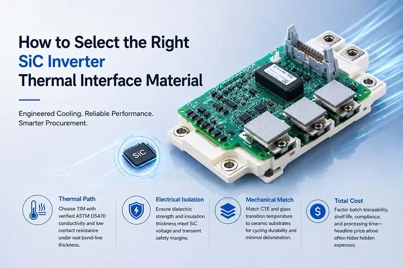
This image is a conceptual illustration and does not represent the actual appearance, size, or internal structure of the product.
Quick Answers for SiC Inverter Thermal Interface Material
➔ Thermal Path: Choose TIM with verified ASTM D5470 conductivity and low contact resistance under real bond‐line thickness.
➔ Electrical Isolation: Ensure dielectric strength and insulation thickness meet SiC voltage and transient safety margins.
➔ Mechanical Match: Match CTE and glass transition temperature to ceramic substrates for cycling durability and minimal delamination.
➔ Total Cost: Factor batch traceability, shelf life, compliance, and processing time—headline price alone often hides hidden expenses.
5 Key Factors for Selecting Thermal Interface Materials
Choosing a SiC inverter thermal interface material comes down to more than chasing a high conductivity number. Heat flow, insulation, mechanical fit, and cycling life all matter once a SiC power module starts working hard. Sheen Technology evaluates these linked properties so an inverter TIM can keep temperatures manageable without making assembly, safety, or long-term reliability a headache.
Thermal Conductivity: From Silicone Pad to Graphite Sheet
For a SiC inverter thermal interface material, compare both bulk thermal conductivity and interface behavior.
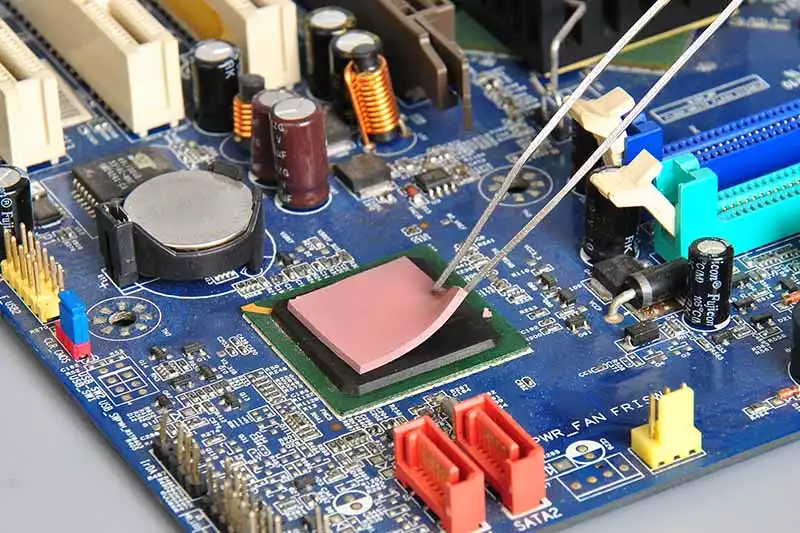
Soft interfaces
- silicone pad: easy gap filler, electrically insulating.
- grease or phase change material: typically lowers contact resistance.
High-conductivity interfaces
- graphite sheet: excellent in-plane heat transfer, but normally conductive electrically.
- Thickness and mounting pressure still determine real thermal resistance.
Dielectric Strength Requirements for Wide Bandgap Devices
A wide bandgap silicon carbide inverter can see sharp switching spikes. The SiC inverter thermal interface material therefore needs enough dielectric strength and breakdown voltage for the working insulation voltage, transient voltage stress, and safety margin. Good electrical isolation must also survive compression and aging.
Thermal Impedance Impact on Inverter Baseplate Efficiency
Sheen Technology considers the full heat path rather than a TIM datasheet value alone:
| Interface factor | Typical value | Unit | Thermal effect |
| TIM thickness | 0.10 | mm | lower is often better |
| Conductivity | 5 | W/m·K | improves transfer |
| Contact resistance | 0.10 | cm²·K/W | raises temperature |
| Baseplate temperature | 85 | °C | affects cooling margin |
Total thermal impedance
- TIM contact resistance
- inverter baseplate spreading
- heat-sink heat dissipation
Lower resistance reduces junction temperature, helping power module thermal performance.
Glass Transition Temperature in Phase Change Material
- Check glass transition temperature and melting point.
- Confirm viscosity drops enough to wet microscopic gaps.
- Verify the polymer matrix, latent heat, and thermal stability remain suitable through cycling.
A SiC thermal interface needs predictable softening, not messy pump-out.
Coefficient of Thermal Expansion and Ceramic Substrate Compatibility
The coefficient of thermal expansion should work with the ceramic substrate and direct-bonded copper stack.
During thermal cycling
- mismatch creates thermal stress;
- compliant TIM reduces mechanical fatigue;
- lower strain helps prevent delamination.
For SiC inverter thermal interface material selection, that mechanical match can matter just as much as headline conductivity.
Layer 2: Thermal Conductivity Ratings Demystified
Selecting a SiC inverter thermal interface material takes more than checking a conductivity number. Test method, contact pressure, thickness, and cooling design all matter. Sheen Technology helps engineers compare SiC thermal interface options on practical, like-for-like terms.
Test method comparison:
| Method | What It Measures | Standard | Best Use |
| ASTM D5470 (steady-state) | Through-plane thermal resistance/conductivity under pressure | ASTM D5470 | PRIMARY — captures bulk + contact resistance |
| Laser Flash | Thermal diffusivity → calculated conductivity | ASTM E1461 | Complementary — no contact resistance |
| Hot Disk (transient) | Thermal conductivity + diffusivity | ISO 22007-2 | Complementary — different heat-flow geometry |
ASTM D5470: Benchmarking Thermal Conductivity
ASTM D5470 is a steady-state method that drives controlled heat flux through a sample and measures its temperature gradient. That makes SiC inverter thermal interface material comparisons far more useful than headline ratings alone.
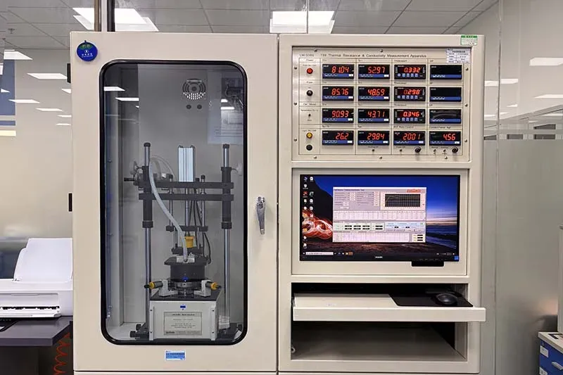
Test the real stack:
- Control material thickness and mounting pressure.
- Compare measured thermal impedance.
Check contact effects:
- Separate bulk behavior from interface resistance where the data permits.
- Keep the testing standard and setup consistent; otherwise, it’s apples to oranges.
For SiC inverter thermal interface material screening, those controls help expose performance that a datasheet number can hide.
Laser Flash Analysis versus Hot Disk Method
Laser Flash Analysis applies pulsed energy and derives thermal diffusivity; conductivity calculations also require density and specific heat capacity. Hot Disk, covered within ISO 22007 methods, uses a sensor probe for transient measurement.
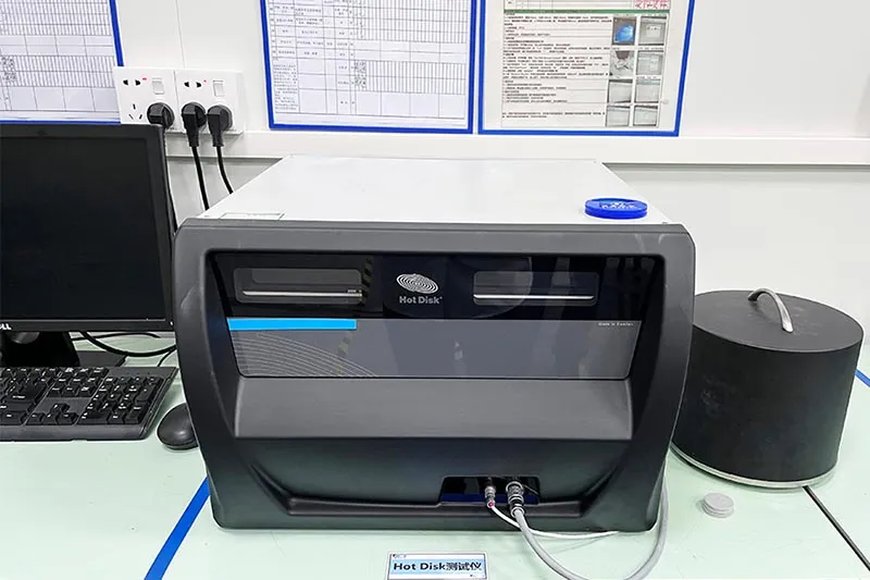
The catch? Ambient temperature, specimen geometry, contact quality, and testing speed can shift results. So compare method with method when judging SiC inverter material data, not just the final W/m·K figure.
From 1 to 10 W/m·K: Choosing the Right Grade
A higher bulk thermal conductivity can help, but 10 W/m·K is not automatically the sweet spot.
- Start with the silicon carbide power module:Estimate heat load and target junction temperature.
- Model the TIM layer:Use bond-line thickness and thermal resistance alongside conductivity.
- Check the cooling stack:Better heat dissipation may make a lower performance grade sufficient.
Sheen Technology can match SiC inverter thermal interface material grades to mechanical, thermal, and cost targets rather than chasing one flashy number.
How Does TIM Thickness Affect Heat Flow?
A SiC inverter thermal interface material needs a controlled gap, steady flow, and close surface contact to move heat into the cooler efficiently. Sheen Technology focuses on these practical details because small interface flaws can, quite literally, turn into hot problems.
Bond Line Thickness and Heat Sink Performance
Bond thickness sets the basic heat path for a SiC inverter thermal interface material.
A thinner bond line thickness generally lowers thermal resistance and improves heat dissipation.
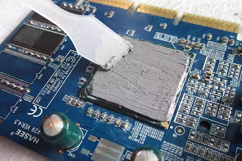
Going too thin can leave uncovered spots.
- Proper interface pressure helps maintain contact conductance between the inverter baseplate and heat sink.
- Complete coverage keeps overall thermal impedance in check.
The goal is simple: thin, but not so thin that gaps sneak in.
Dispensing Viscosity’s Role in Uniform Coverage
For SiC inverter thermal interface material, viscosity must suit the dispenser and interface gap. Good rheology, meaning controlled flow behavior, supports predictable dispensing.
- Apply enough material for gap filling without messy overflow.
- Check material flow as the parts clamp together.
- Confirm uniform coverage and look for trapped air or voids.
A well-matched SiC thermal interface compound spreads reliably without making production a headache. Sheen Technology can match SiC inverter thermal interface material properties with practical application needs.
Surface Roughness Impact on Thermal Impedance
Real mating surfaces contain peaks and valleys called asperities.
Higher surface roughness can reduce true contact area.
- Small gaps become microscopic voids or interface traps.
- A compliant TIM fills these spaces under realistic clamping force.
Surface flatness matters too.
- Better contact helps lower thermal impedance, giving a SiC inverter a cleaner path for heat transfer.
Automotive SiC Inverters: TIM in Harsh Conditions
A SiC inverter thermal interface material faces heat, motion, storage, and safety demands that can change thermal performance over time. Qualification therefore needs more than a good datasheet number. Sheen Technology supports SiC inverter programs by connecting material selection with realistic thermal, mechanical, and environmental checks before production gets rolling.
Thermal Shock Testing for EV Powertrain Reliability
Rapid hot-to-cold transitions can expose weak spots in a silicon carbide inverter that steady testing may miss.
Thermal cycling evaluation
- Track thermal conductivity before and after repeated shocks.
- Inspect the SiC inverter thermal interface material for cracking, delamination, and interface degradation.
Reliability review
- Relate physical damage to thermal fatigue and changing junction temperatures.
- Check stress resistance against the expected vehicle duty cycle and powertrain reliability targets.
This section quotes the reliability test report from Sheen Technology's laboratory regarding the SF1000 thermal conductive silicone pad:
Test conditions:
| Test Item | Test Conditions | Test Equipment |
| High-Temperature Aging | 125℃, 1000H | Precision Oven |
| Constant Temperature & Humidity | 85℃, 85%RH, 1000H | Constant Temperature & Humidity Chamber |
| Thermal Shock | −40℃∼125℃, 1000H | Thermal Shock Chamber |
Evaluation criteria:
| Property | Initial Value | Acceptance Criteria |
| Thermal Conductivity(W/m·k) | 10.13 | ±15% |
| Hardness(Shore 00) | 72 | ±10% |
| Pressure (20% compression) psi | 31.4 | ±60% |
| Appearance | Smooth surface, uniform color | No powdering, discoloration, or other abnormalities |
High Temperature Aging Test Record Sheet:
| Test Item | Unit | 0 h | 200 h | 400 h | 600 h | 800 h | 1000 h | Biggest change | Judgement |
| Thermal Conductivity | W/(m⋅K) | 10.13 | 10.40 | 10.58 | 10.71 | 10.62 | 10.73 | 5.9% | Pass |
| Hardness | Shore 00 | 72 | 75 | 76 | 77 | 77 | 78 | 6 | Pass |
| Pressure(@20%) | Psi | 31.4 | 34.3 | 36.6 | 39.5 | 38.7 | 40.5 | 9.1% | Pass |
Constant Temperature and Humidity Test Record Sheet:
| Test Item | Unit | 0 h | 200 h | 400 h | 600 h | 800 h | 1000 h | Biggest change | Judgement |
| Thermal Conductivity | W/(m⋅K) | 10.13 | 10.58 | 10.77 | 10.85 | 10.64 | 10.77 | 7.1% | Pass |
| Hardness | Shore 00 | 72 | 74 | 76 | 77 | 77 | 77 | 5 | Pass |
| Pressure(@20%) | Psi | 31.4 | 34.3 | 36.6 | 38.4 | 39.7 | 39.2 | 7.8% | Pass |
Cold and Thermal Shock Test Record Sheet:
| Test Item | Unit | 0 h | 200 h | 400 h | 600 h | 800 h | 1000 h | Biggest change | Judgement |
| Thermal Conductivity | W/(m⋅K) | 10.13 | 10.64 | 10.88 | 10.75 | 10.67 | 10.80 | 7.4% | Pass |
| Hardness | Shore 00 | 72 | 72 | 74 | 75 | 75 | 76 | 4 | Pass |
| Pressure(@20%) | Psi | 31.4 | 31.4 | 34.8 | 37.9 | 40.2 | 41.9 | 10.5% | Pass |
Test conclusion: SF1000 performed OK under various aging conditions for 1000 hours, with no change in appearance. Therefore, the SF1000-70° reliability test is qualified. That keeps qualification tied to real operating stress, not just initial performance.
Storage Condition and Shelf Life under High Vibration
Storage comes before vibration testing. A thermal interface material, especially grease or phase change material, should remain within its stated shelf life while sealed packaging integrity protects it from contamination.
After assembly, test mechanical vibration and dynamic stress separately. Measure bondline thickness, watch for migration or pad movement, and verify material stability after testing. Sheen Technology can help match SiC thermal interface options to these practical handling and durability needs.
UL94 V-0 and Environmental Certification for Safety
Qualification should connect product documentation with the exact automotive application.
Safety documentation
- Confirm the applicable UL94 flammability rating and safety standard.
- Verify required electrical insulation properties.
Environmental documentation
- Check RoHS and REACH regulatory compliance.
- Confirm halogen-free claims where specified.
- Review customer-specific environmental certification evidence.
A SiC inverter thermal interface material should be approved against its documented grade and use conditions rather than assuming every TIM carries identical certifications.
SiC Inverter Thermal Interface Material Cost Traps
Choosing a SiC inverter thermal interface material by price alone can look like a sweet deal, but then extra manufacturing costs start piling up. SiC inverter programs also depend on paperwork, handling, compliance, and processing speed. Sheen Technology helps buyers compare inverter thermal interface options by total applied cost, so thermal material choices fit both production targets and long-term automotive quality needs.
Hidden Fees in Batch Traceability and Packaging Specification
Purchasing costs
- A low kilogram price may exclude inspection fee, incoming testing, or controlled storage.
- Small-volume orders can also carry higher minimum order quantities.
Traceability costs
- Each lot code should connect to quality documentation and a certificate of analysis.
- Custom packaging and a special labeling requirement add expense but can simplify line control.
For a SiC inverter thermal interface material, the useful number is total delivered-and-qualified cost, not the headline material price.
Balancing RoHS Compliance with Budget Constraints
Cheap SiC thermal material can get pricey fast when global approval work enters the mix.
- Check RoHS limits for each hazardous substance and review REACH environmental regulation duties.
- Request a current material declaration plus supporting compliance documentation.
- Compare any alternative compound against added regulatory testing, qualification work, supply risk, and possible inverter redesign.
Sheen Technology can support documentation review alongside material selection, helping procurement avoid a bargain that backfires later.
Curing Time versus Clamping Pressure: Cost vs. Performance
Process economics
- Shorter polymerization can raise assembly throughput and cut the production cycle.
- Less fixture time also reduces curing energy.
Interface performance
- Higher thermal conductivity alone does not guarantee low thermal impedance.
- Controlled bond line thickness matters.
Reliability limits
- Excess clamping creates mechanical stress.
- A phase change thermal interface may simplify processing, but pressure and temperature still need validation.
The best SiC inverter thermal interface material balances line speed with a uniform, durable interface.
SiC inverter TIM selection requires balancing thermal conductivity, dielectric strength, thermal impedance, mechanical compatibility, and total applied cost — all validated under wide-bandgap operating conditions. Sheen Technology supports the selection with ASTM/IEC-referenced test data, application-specific recommendations, and cost modeling to ensure production-ready SiC thermal management.
→ Contact Sheen Technology for SiC Inverter TIM Selection Support
Sheen Thermal
Dongguan Sheen Electronic Technology Co., Ltd · Founded in 2008
Manufacturer of thermal interface materials and silicone foam for automotive electronics, energy storage, power electronics, communications and consumer electronics.
Certified
- ISO 9001:2015
- ISO 14001:2015
- IATF 16949:2016
What we supply
- Thermal conductivity Up to 90 W/m·K
- Thickness 0.3–10.0 mm
- Custom & samples Die-cut to drawing, 3–7 days