
 English
 usheenthermal

Mastering 5G Equipment Graphite Thermal Pad Heat Dissipation Design
Date:2026-07-07
Mastering 5G Equipment Graphite Thermal Pad Heat Dissipation Design
Heat is choking modern networks, and the 5G equipment graphite thermal pad heat dissipation solution steps in like a calm fixer.
When hardware runs hot, performance dips, signals wobble, and maintenance bills creep up fast.
GSMA and IDC reports highlight thermal management demand in 5G infrastructure, favoring graphite pads.
Quick Insights: 5G Equipment Graphite Thermal Pad Heat Dissipation Solution
1)Understand Heat Spreading: Pyrolytic graphite pads excel at in-plane conductivity, dispersing intense PA and SoC hotspots evenly across heat sinks.
2)Ensure Long-Term Stability: Unlike thermal grease, graphite pads maintain low and consistent thermal resistance over cycles, preventing pump-out and signal drift.
3)Optimize Component Uptime: Thin graphite sheets conform to gaps in RF modules, baseband processors, and antenna arrays, reducing thermal throttling and extending device lifespan.
Why 5G Equipment Graphite Thermal Pad Heat Dissipation Solution Matters
5G base stations run hot, and not in a cool way. As traffic surges, chips push harder, and heat builds fast. A reliable 5G equipment graphite thermal pad heat dissipation solution keeps signals stable and hardware safe. By pairing smart thermal management with advanced graphite materials, engineers can control heat transfer without slowing down high-frequency performance.
Understanding heat flux in Power Amplifiers and SoCs
High heat flux in a power amplifier and SoC comes from tiny silicon areas pushing serious current. In dense electronics, this means focused hot zones that stress solder joints and substrates.
At the chip level
· Heat transfer starts at the die surface.
· Limited area raises local temperature fast.
· Uneven spreading increases thermal gradients.
At the module level
· Concentrated heat loads the lid and heat spreader.
· Poor in-plane conduction traps energy near the source.
· RF drift appears as temperature climbs.
At the system level
· Fans and sinks depend on lateral spreading.
· Without graphite layers, hotspots persist.
A tuned 5G equipment graphite thermal pad heat dissipation solution improves overall thermal management.
Pyrolytic graphite, known for strong in-plane conductivity, spreads flux sideways before it reaches the sink, making the whole stack behave calmer under peak loads.
Graphite thermal pad vs. grease: impact on thermal resistance
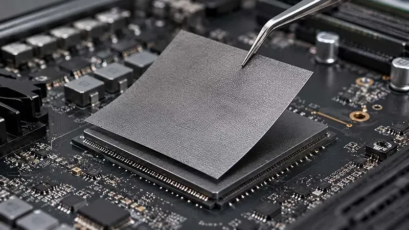
When comparing graphite thermal pad and thermal grease, engineers care about thermal resistance and long-term heat dissipation.
· Grease fills gaps well at the start.
· Pump-out can occur after thermal cycling.
· Contact pressure changes performance over time.
In contrast, a graphite thermal pad acts as a stable interface material with predictable thermal conductivity. It resists dry-out and keeps thickness consistent.
Key comparison points:
· Stability across temperature swings.
· Mechanical durability under vibration.
· Clean assembly without rework mess.
A solid 5G equipment graphite thermal pad heat dissipation solution reduces impedance drift, which helps PAs stay within spec.
“Thermal interface reliability is becoming a defining factor in 5G infrastructure uptime,” noted a 2025 thermal materials outlook by Yole Group, highlighting growing demand for graphite-based solutions.
For designers seeking repeatable results, Sheen Technology provides engineered graphite pads tailored to RF stacks, aligning heat dissipation targets with assembly realities.
Improving uptime of RF modules with graphite sheets
Keeping an RF module alive under constant load takes more than a fan. A focused 5G equipment graphite thermal pad heat dissipation solution with a high-quality graphite sheet supports real reliability in 5G equipment.
Here’s how it plays out:
· Identify hotspot zones on the PA and transceiver.
· Integrate a graphite sheet to spread heat dissipation laterally.
· Match compression force to maintain interface contact.
· Validate temperature drop under full-band transmission.
· Monitor long-term uptime during continuous operation.
Less hotspot stress means fewer shutdowns. Less throttling means steadier throughput. That’s the practical edge operators want.
With application-driven designs from Sheen Technology, teams can deploy a repeatable 5G equipment graphite thermal pad heat dissipation solution that supports uptime goals without overcomplicating system layouts.
3 Key Benefits of Graphite Thermal Pad Solutions
5G hardware runs hot, and cooling isn’t just nice to have—it keeps networks stable. A well-designed 5G equipment graphite thermal pad heat dissipation solution helps manage rising power loads while keeping signal performance steady and reliable.
Superior thermal conductivity for high-power transceivers
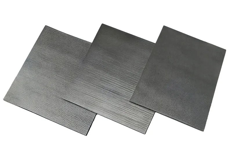
High thermal conductivity drives fast heat transfer away from high power transceivers and dense RF modules. In a typical 5G equipment graphite thermal pad heat dissipation solution, graphite works like a heat highway.
Material Layer Performance
1.1 Synthetic Graphite
· In-plane thermal conductivity up to 1500 W/m·K
· Optimized for rapid power dissipation
1.2 Graphene-Enhanced Composites
· Lower interface resistance
· Improved thermal management in compact radios
System-Level Impact
2.1 Heat Flow Path
· Chip → graphite pad → vapor chamber
· Reduced hotspot buildup
2.2 Device Outcome
· Stable device performance
· Longer component lifespan
| Properties | Unit | GSF75-03 Graphene Thermal Pad | GSF90-03 Graphene Thermal Pad | Test Method |
| Color | - | Black | Black | Visual |
| Thermal Conductivity | W/m·K | 75 | 90 | ASTM E1461 |
| Thermal Resistance (@40psi) | ℃*cm2/W | ≤0.12 | ≤0.10 | ASTM D5470 |
| Thickness | mm | 0.3~2.0 | 0.3~2.0 | ASTM D374 |
| Density | g/cm³ | 0.3~0.7 | 0.3~0.7 | ASTM D792 |
| Rebound Rate | % | ≥90 | ≥90 | - |
| Tensile Strength | Mpa | ≥0.03 | ≥0.05 | ASTM D412 |
| Oil Bleeding Rate | % | ≤3 | ≤3 | / |
| Application Temperature | ℃ | -40~150 | -40~150 | / |
| Flame rating | - | - | V-0 | UL 94 |
This data shows why the 5G equipment graphite thermal pad heat dissipation solution is becoming standard in advanced base stations. Sheen Technology tunes thickness and conductivity to match real RF loads, not just lab specs.
Low thermal impedance to stabilize baseband processors
Low thermal impedance keeps baseband processors calm under pressure. When junction temperatures swing, processor stability drops and signal timing drifts. A tight thermal interface fixes that.
• Reduced heat resistance between IC and heat spreader
• Better temperature control during peak data bursts
• Stronger system reliability in outdoor cabinets
In practical deployments, the 5G equipment graphite thermal pad heat dissipation solution forms a short, efficient heat transfer path. Step by step, heat leaves the chip, crosses a thin graphite layer, and spreads across aluminum housing.
“Thermal density in 5G radio units continues to increase as spectrum efficiency improves,” notes a 2025 GSMA infrastructure outlook, stressing that advanced materials are key to maintaining uptime in dense networks.
For operators, stable IC cooling means fewer resets and smoother throughput. For designers, it means tighter layouts without gambling on overheating.
Enhanced compressibility for optimal gap filling
Not every surface is perfectly flat. That’s where compressibility and smart gap filling matter in a 5G equipment graphite thermal pad heat dissipation solution.
Interface Adaptation
1.1 Material Behavior
· High material conformability under pressure
· Fills surface irregularities
1.2 Contact Improvement
· Lower contact resistance
· Stronger thermal contact with copper or aluminum
Assembly Benefits
2.1 Installation
· Easy alignment with pressure-sensitive adhesive
· Clean bonding, minimal rework
2.2 Long-Term Operation
· Stable heat transfer path
· Reduced air gaps over time
Sheen Technology High Rebound Graphene Thermal Pads Performance Testing
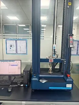
· Test Standard: ASTM D575.
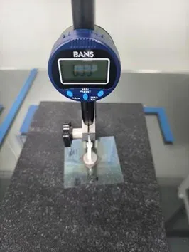
· Sample Preparation: Material specimens measuring 25 mm × 25 mm × 0.3 mm.
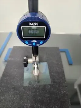
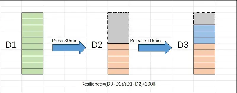
· Test Method: Zero the force reading before testing; apply a 2 N force to contact the sample surface. Set the compression speed to 0.5 mm/min and compress to 50% deformation. Maintain the load for 30 minutes. Let D1 be the initial thickness and D2 be the thickness after compression; measure the thickness again as D3 after a 10-minute recovery period. Calculate the recovery rate as (D3 - D2) / (D1 - D2) × 100%.
| Testing Equipment | Before Testing | After Testing |
 |
 |
 |
| Test Item | Test Data | |||
| 1 | 2 | 3 | Average Value | |
| Rebound Rate(%) | 92 | 94 | 95 | 93 |
When the pad compresses just right, the whole 5G equipment graphite thermal pad heat dissipation solution performs better. Sheen Technology engineers balance softness and strength so the pad doesn’t pump out or dry up after long field use.
Which 5G Equipment Suits Graphite Thermal Pad Solution
5G runs hot, and nobody likes overheated gear. A smart 5G equipment graphite thermal pad heat dissipation solution keeps systems steady, fast, and reliable. Here’s how different hardware benefits when heat is handled the right way.
Power amplifiers (PAs)
Power amplifiers (PAs) sit at the heart of RF power delivery, pushing high frequency signals across networks. That output raises junction temperature fast, especially in gallium nitride (GaN) designs built for higher efficiency and sharper linearity.
Core thermal risks
Heat buildup inside GaN die
· Rising thermal resistance between chip and case
· Local hotspots reducing signal stability
Board-level stress
· Uneven heat spreading across copper layers
How a 5G equipment graphite thermal pad heat dissipation solution responds
· Transfers heat from die to heat sink interface
· Spreads thermal load laterally across MCPCB
· Lowers junction temperature to protect RF output
A thin graphite thermal interface from Sheen Technology keeps performance steady without adding bulk. In short, better heat flow equals cleaner RF power.
RF modules
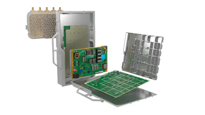
Inside compact RF modules, every transceiver and integrated circuit shares tight space. That’s where a 5G equipment graphite thermal pad heat dissipation solution earns its keep.
Thermal pressure points
· Dense signal chain routing
· Limited airflow in compact packaging
· Crosstalk risks tied to electromagnetic interference (EMI)
Functional requirements
· Stable thermal interface to substrate
· Dielectric strength for high frequency paths
· Compatibility with module integration layouts
A graphite heat dissipation pad handles localized peaks without disturbing the RF substrate.
GSMA’s 2025 mobile infrastructure outlook notes that higher-band 5G radios “intensify thermal density at the module level, demanding advanced interface materials.”
That insight lines up with field reality. Sheen Technology fine-tunes graphite thickness so RF modules stay cool and signal integrity remains intact.
Baseband processors
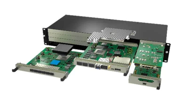
The baseband processors manage digital processing at extreme data rate and rising clock frequency. When a system-on-chip (SoC) runs flat out, thermal throttling can quietly drag performance down.
Heat sources
· Multi-core processor core clusters
· High-speed memory controllers
Cooling path design
· SoC surface
· Graphite thermal pad
· Heat sink interface
· Chassis spreader
A stable 5G equipment graphite thermal pad heat dissipation solution smooths temperature swings. Less thermal cycling means longer solder joint life. The device keeps crunching data without surprise slowdowns.
Antenna arrays
Antenna arrays, especially massive MIMO, combine many active elements within one radiating structure. Add beamforming and precise phase control, and heat builds unevenly across the panel.
Array-level challenges
· Edge-to-center temperature gradients
· Outdoor exposure demanding environmental resilience
Thermal management strategy
· Wide-area graphite sheets:Promote balanced heat spreading,Support overall array efficiency
· Direct bonding to backplane:Reduce hotspots behind active elements
A 5G equipment graphite thermal pad heat dissipation solution ensures balanced thermal management across the full antenna face. That steady temperature profile keeps array efficiency high and performance consistent, even during peak traffic hours.
Sheen Thermal
Dongguan Sheen Electronic Technology Co., Ltd · Founded in 2008
Manufacturer of thermal interface materials and silicone foam for automotive electronics, energy storage, power electronics, communications and consumer electronics.
Certified
- ISO 9001:2015
- ISO 14001:2015
- IATF 16949:2016
What we supply
- Thermal conductivity Up to 90 W/m·K
- Thickness 0.3–10.0 mm
- Custom & samples Die-cut to drawing, 3–7 days