
 English
 usheenthermal

Future-Proofing AI: Cooling Solutions for 3.2T Optical Transceivers
Date:2026-09-18
Cooling solutions for 3.2T optical transceivers are becoming a thermal pressure point: AI bandwidth climbs, while tiny modules must move serious heat without cooking performance.
The IEA’s 2025 Energy and AI report projects global data-center electricity demand to reach about 945 TWh by 2030, more than double 2024 levels.
That heat must go somewhere; success lies in matching TIMs, substrates, bonding materials, and cooling hardware at production scale.
Quick Notes & Key Points for Cooling solutions for 3.2T optical transceivers
➔ Match TIMs and substrates: choose high-κ materials (silicone grease, gap pads, graphite sheets) to minimize interfacial resistance.
➔ Substrate choice matters: aluminum nitride offers superior conduction over alumina ceramic under dense heat loads.
➔ Air vs. liquid: traditional heatsinks and heat pipes suffice up to a point; microchannel cold plates deliver 40% temperature reduction in high-flux scenarios.
➔ Bonding & sealing: employ conductive epoxy or silver epoxy for cold-plate attachment, plus robust molding compounds to ensure leak-free operation.
➔ Scalable architectures: leverage modular vapor chamber arrays or stacked heat-pipe manifolds to support growing AI port densities.

Note: This image was generated with the assistance of AI; it is not a real photograph and is for reference only.
What Thermal Challenges Do 3.2T Transceivers Face?
Cooling solutions for 3.2T optical transceivers must handle rising power inside very tight spaces. Dense optics, DSPs, and interfaces can push temperatures up fast, so efficient heat paths really matter. Sheen Technology addresses these thermal challenges by matching cooling design with package materials and component placement.
Hot Spots from High-Density Silicon Substrates
High-density integration packs major heat sources onto a compact silicon substrate, making local control tricky.
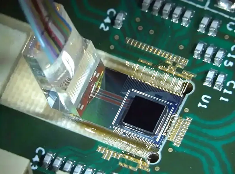
DSP and optical-engine zones
- Rising junction temperature can approach semiconductor thermal limits.
- Better thermal dissipation spreads energy before one area gets too hot.
Cooling response
- Hot spot mitigation can combine heat spreaders with micro-channel cooling where practical.
Cooling solutions for 3.2T optical transceivers therefore need targeted 3.2T cooling, not just more airflow.
Heat Flux Peaks on Alumina Ceramic Substrate Interfaces
Alumina ceramic provides useful electrical insulation, yet its thermal conductivity can limit heat transfer compared with higher-conductivity ceramics.
At the package
- Concentrated heat flux moves from chips into substrate packaging.
At the cooler boundary
- A poorly fitted thermal interface material adds interface resistance.
- Temperature differences can also increase thermal stress.
Cooling solutions for 3.2T optical transceivers work better when interface thickness and contact quality are kept in check.
3 Key Factors In Transceiver Cooling Efficiency
Cooling solutions for 3.2T optical transceivers must move concentrated heat away quickly without creating packaging headaches. Good thermal design comes down to interface contact, substrate choice, and cooling hardware. Get those pieces right, and Heat Dissipation improves while hot spots stay in check. Poor matching, by contrast, can push temperatures up fast.
Thermal Interface Materials: Comparing Silicone Grease and Gap Pads
For Cooling solutions for 3.2T optical transceivers, Thermal Interface Materials close tiny air gaps between hot parts and coolers.

- Forms a thin bond line, supporting efficient Heat Transfer.
- Low Thermal Resistance suits flat, tightly controlled surfaces.
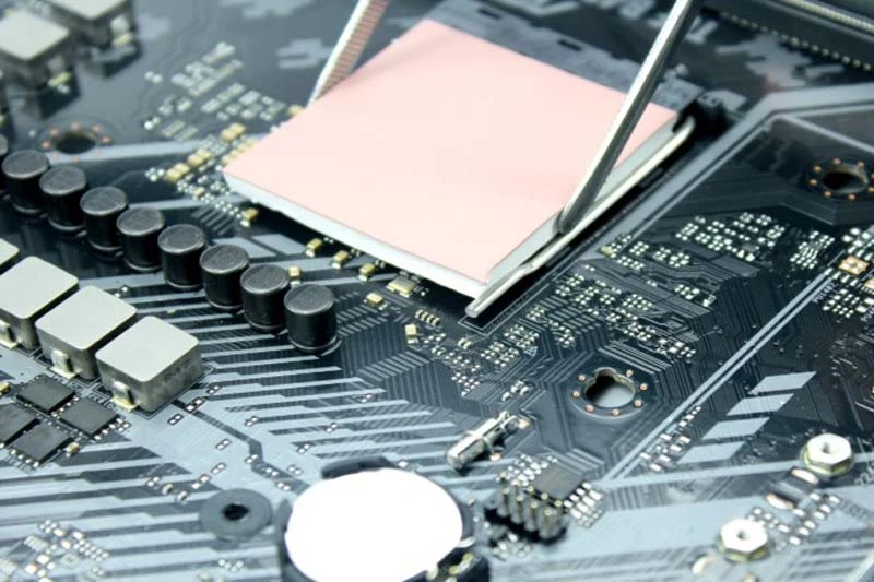
- Handle height variation and rough surfaces more easily.
- Extra thickness can reduce effective Thermal Conductivity.
Assembly needs
- Higher Interface Pressure can improve contact, but mechanical limits matter. In short, tighter is not always better.
Substrate Thermal Conductivity of Aluminum Nitride vs. Silicon
Cooling solutions for 3.2T optical transceivers also depend heavily on the Substrate.
Aluminum Nitride combines strong Thermal Conductivity with electrical insulation, making dense packaging easier to manage. Silicon also conducts heat effectively and fits established semiconductor processes, though its electrical behavior changes packaging choices.
For either material, key Material Properties determine the Temperature Gradient from the heat source to the cooler. Lower gradients generally support better Heat Dissipation and steadier optical operation.
Impact of Cooling Hardware Components on Heat Dissipation
Cooling solutions for 3.2T optical transceivers need Cooling Hardware matched to heat flux, space, and available Airflow.
Passive and air-cooled
Heat Sink
- Aluminum fins offer practical weight and cost.
- Performance depends strongly on airflow.
Heat pipes
- Move heat toward larger fin areas, improving Thermal Performance.
Higher heat-flux options
Vapor chambers
- Spread concentrated heat across a wider area.
Microchannel cold plates
- Support liquid-based Thermal Management where air cooling runs out of steam.
- Lower thermal resistance helps control Junction Temperature in demanding 3.2T transceiver cooling designs.
Air Cooling Vs. Liquid Cooling For Transceivers
Cooling solutions for 3.2T optical transceivers must handle high heat in a very small space while keeping optics within safe operating temperatures. Air cooling remains familiar and easy to service, while liquid cooling targets hotter, denser AI systems. In practice, picking the right 3.2T transceiver cooling method comes down to rack density, facility design, noise, and maintenance needs.
Air Cooling
Cooling solutions for 3.2T optical transceivers can still rely on air when rack conditions leave enough thermal headroom.
Air path
- A finned aluminum heat sink spreads heat over a larger surface. Lower thermal resistance helps the module move heat out quickly.
- Higher airflow velocity improves heat removal, but there’s a catch: fan noise and electrical demand rise.
Rack conditions
- The fan configuration should prevent hot exhaust from returning to transceiver inlets.
- Ambient temperature directly affects available cooling margin, while a good thermal interface material reduces contact losses.
| Inlet air | Air speed | Module heat | Typical pressure |
| 25°C | 2 m/s | 25 W | 80 Pa |
| 30°C | 3 m/s | 30 W | 120 Pa |
| 35°C | 4 m/s | 35 W | 170 Pa |
*These values are engineering comparison points, not universal operating limits.
Liquid Cooling
For dense AI racks, Cooling solutions for 3.2T optical transceivers may shift heat into liquid loops, cutting dependence on very fast chassis fans.
Heat collection
- A cold plate places the coolant fluid close to concentrated heat sources.
- A micro-channel design increases wetted surface area and shortens the conduction path.
System operation
- High fluid thermal conductivity supports efficient heat transfer.
- Pump reliability and leak detection become key service concerns. That trade-off is pretty practical: less airflow pressure, but extra plumbing to manage.
Deployment
- Direct-liquid designs suit localized cooling, while immersion cooling places compatible hardware in dielectric fluid.
These liquid-cooled transceiver approaches make sense where air cooling hits practical power-density limits.
Data Shows: Liquid Cooling Cuts Optical Transceiver Temps By 40%
Cooling solutions for 3.2T optical transceivers need measurement, not guesswork. Heat-flux, infrared, and material tests show how liquid cooling controls temperature as AI networking power climbs.
Calibrated Heat Flux Sensor Measurements on Copper Heat Pipes
Heat flux measurements establish how much energy actually moves through copper heat pipes.
Sensor calibration keeps air- and liquid-cooling comparisons on equal footing.
- Measured temperature gradient and thermal resistance expose limits in heat dissipation.
- High thermal conductivity helps heat travel quickly, but coolant still needs to carry it away.
Cooling solutions for 3.2T optical transceivers can then be judged using repeatable data, rather than a best-case temperature reading. Pretty handy when every degree counts.
Infrared Thermography Target Reports for Vapor Chambers
Infrared thermography turns emitted infrared energy into a temperature map, making uneven heat distribution easy to spot.
- Consistent targets improve thermal imaging accuracy on vapor chambers.
- Surface temperature maps support hotspot detection beside optical engines and control electronics.
- Comparing maps before and after cooling changes provides a practical check on thermal performance.
For Cooling solutions for 3.2T optical transceivers, these maps show exactly where liquid cooling solutions cut optical-transceiver heat instead of merely shifting it nearby.
Differential Scanning Calorimetry Pan Analysis of Phase Change Materials
DSC heats small phase change material samples under controlled conditions.
- The resulting curve identifies melting point and latent heat.
- Integrated heat flow gives enthalpy data.
Repeated cycles then assess:
- Thermal capacity during workload spikes.
- Thermal stability after repeated melting and solidifying.
Cooling solutions for 3.2T optical transceivers may pair such thermal buffering with liquid cooling, smoothing brief AI-networking power peaks before steady cooling catches up.
Data Center: Scalable Cooling For 3.2T Transceivers
Cooling solutions for 3.2T optical transceivers must manage rising optical heat without making rack design a headache. Sheen Technology pairs practical thermal hardware with scalable airflow planning, helping dense AI systems keep transceiver temperatures steady as port counts climb.
Modular Vapor Chamber Arrays
A vapor chamber spreads heat through phase change, giving compact 3.2T optical transceivers a wider cooling footprint.
- At the evaporator interface, working fluid absorbs heat.
- A condenser wick returns liquid through capillary flow.
This thermal spreading approach makes Cooling solutions for 3.2T optical transceivers easier to repeat across dense trays.
Stacked Copper Heat Pipe Manifolds
A stacked copper heat pipe network moves heat toward shared cooling zones with low thermal resistance. High thermal conductivity supports fast heat transfer, while smart manifold design keeps the setup tidy.
- Better capillary action supports reliable heat dissipation.
- Balanced fluid dynamics help prevent hot spots. Pretty handy when optical density rises.
Thermoelectric Cooler Rack Integration
Temperature control
- A Peltier module provides targeted active cooling for sensitive optics.
- The thermoelectric cooler responds quickly to changing heat flux.
Power planning
- Good power regulation limits wasted electricity.
- The Seebeck effect helps explain the underlying thermoelectric behavior.
Aluminum Extruded Heatsink Bank Design
Aluminum extrusion keeps large heatsink banks practical and cost-effective.
- Fin geometry increases useful surface area.
- Airflow optimization improves convective cooling without excessive fan pressure.
- Thermal interface material cuts contact losses.
For Cooling solutions for 3.2T optical transceivers, Sheen Technology can match each heatsink array to rack airflow and optical cooling needs, keeping scalable 3.2T cooling straightforward.
【Request a Custom Quote】Weighing air cooling against liquid cooling for dense 3.2T line cards? Send us your module power map, inlet air conditions, target junction temperature, substrate and TIM stack-up, and cold-plate or heat-pipe constraints, and our engineers can recommend cooling solutions for 3.2T optical transceivers that hold up as bandwidth scales.
Sheen Thermal
Dongguan Sheen Electronic Technology Co., Ltd · Founded in 2008
Manufacturer of thermal interface materials and silicone foam for automotive electronics, energy storage, power electronics, communications and consumer electronics.
Certified
- ISO 9001:2015
- ISO 14001:2015
- IATF 16949:2016
What we supply
- Thermal conductivity Up to 90 W/m·K
- Thickness 0.3–10.0 mm
- Custom & samples Die-cut to drawing, 3–7 days
LAST:Nothing