
 English
 usheenthermal

Flexible Phase Change Thermal Conductive Film vs. Traditional Heat Pads
Date:2026-05-28
Flexible Phase Change Thermal Conductive Film vs. Traditional Heat Pads
Heat is killing performance, and Flexible phase change thermal conductive film is stepping in while old pads quietly fall behind in real-world systems.
Procurement teams feel the squeeze as hotter chips, tighter spaces, and rising energy bills turn choices into expensive problems.
Recent reports from Gartner and IDC indicate rising demand for thermal interfaces in centers and EV electronics, favoring phase change materials.
Harmonious Highlights of Flexible phase change thermal conductive film
➔ Superior Thermal Conductivity: Graphite fillers and metallic powders enable rapid heat spreading, reducing hot spots in CPUs, GPUs, and power modules.
➔ Precise Phase Change Control: Paraffin wax tuning stabilizes junction temperatures across varying workloads for consistent performance.
➔ Enhanced Flexibility & Adhesion: The polymer matrix conforms to substrates and heat sinks, minimizing air gaps and boosting reliability.
➔ Long-Term Cost Efficiency: Though initial cost is higher, lower interface thermal impedance and superior lifecycle performance cut total cooling expenses.
Why Phase Change Films Outshine Traditional Pads
Phase change pads can feel “fine” until power spikes hit and temps start seesawing. A Flexible phase change thermal conductive film behaves more like a smart bridge: it softens, fills gaps, and moves heat fast, without the messy pump-out drama.
Superior Thermal Conductivity and Heat Spreading
When thermal conductivity rises, heat spreading stops being wishful thinking and starts becoming predictable. With a Flexible phase change thermal conductive film, the trick is pairing fillers with a matrix that doesn’t choke thermal transfer.
Material choices that push efficiency without killing handling:
Carbon route
· Graphite fillers lift thermal conductivity and widen heat spreading across the die area.
· That wider spread cuts hot spots, helping performance stay steady.
Metal route
· Metallic powders speed thermal transfer, especially when the contact patch is small.
· Better lateral flow means calmer heat dissipation under bursts.
Real-world payoff tied to material properties:
· On power stages and tight IC clusters, a flexible phase film acts like a mini heat “bus,” nudging heat away from the bully component.
· Flexible phase change thermal conductive film setups often feel boring in testing—and boring is good, because temperature maps flatten out.
Phase Change Temperature Tuning with Paraffin Wax
A phase change material isn’t magic; it’s just well-timed physics. Paraffin wax brings clean temperature tuning, because the melting point can be chosen to match the “uh-oh” temperature range of a CPU or GPU.
Here’s how flexible phase change thermal conductive film behavior usually plays out, in plain terms:
· Below the phase point, the interface holds shape, keeping decent contact for day-to-day loads.
· Near the tuned melting point, latent heat soaks up spikes, acting like a thermal speed bump.
· After softening, the film wets surfaces better, improving thermal regulation and contact.
Quick notes people actually care about:
· If tuning is too low, it softens early and can feel mushy.
· If tuning is too high, you miss the sweet spot and thermal management becomes reactive, not proactive.
· Flexible phase change thermal conductive film is popular here because “flexible” plus a reliable phase window keeps junction temps from yo-yoing.
Enhanced Flexibility, Compressibility, and Adhesion
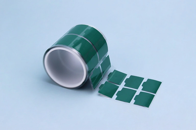
The best conductivity in the world flops if the interface is full of air. A Flexible phase change thermal conductive film leans on the polymer matrix for flexibility and compressibility, so it can press into the tiny surface valleys that pads often skip.
Contact quality, broken down by what actually happens at the joint:
Conformability
· The film bends around package tilt and small height mismatch.
· Better interface contact means fewer “mystery” hot pixels.
Gap filling
· Under clamp load, compressibility helps it flow into microgaps.
· That squeezes out air, the worst-case insulator.
Adhesion
· Light tack keeps placement sane during assembly.
· Stable stick helps during cycling, improving mechanical properties where pads can creep.
In day-to-day builds, flexible phase change thermal conductive film also cuts rework pain—less tearing, fewer crumbs, less fuss.
Lower Interface Thermal Impedance in High-Performance Computing
In high racks, the fight is at the boundary: die → lid → sink. Lower thermal impedance at the interface is the difference between fans screaming and fans coasting, especially in high-performance computing.
Where the heat resistance drops with a Flexible phase change thermal conductive film:
CPU and GPU contact
· Softening improves thermal contact under real clamp pressure.
· Less interfacial voiding means less sudden throttling.
Heat sink mating
· The film’s phase behavior helps it “settle in,” keeping stable contact after thermal cycling.
What changes on the bench (typical comparison targets):
| Material type | Interface thermal impedance (°C·cm²/W) | Typical thickness (µm) |
| Traditional pad | 0.20 | 500 |
| Phase change film | 0.08 | 150 |
| Phase change film (higher filler) | 0.06 | 120 |
| Grease (well-applied) | 0.05 | 50 |
That’s why a flexible phase change thermal conductive film gets picked for dense nodes: it keeps the CPU/GPU to heat sink path consistent, even when workloads swing hard and the system heats, cools, and repeats.
5 Key Factors In Heat Dissipation Films
A Flexible phase change thermal conductive film lives or dies by how it moves heat, stays safe electrically, and holds up for years. Here’s the real-world stuff engineers fuss over, with Sheen Technology building for the messy details.
Factor 1: Reducing Thermal Resistance with Graphite Fillers
When thermal resistance drops, devices calm down fast; with graphite in a composite material, the trick is packing the right filler content without turning the film into a stiff board. That’s why a Flexible phase change thermal conductive film often gets tuned like a recipe, not a spec sheet.
Material levers
· particle orientation: aligned pathways boost thermal conductivity, random packing wastes it
· interfacial resistance: poor bonding blocks phonon transport even with high loading
Process levers
· calendering can nudge particle orientation while keeping thickness honest
· dispersion chemistry trims interfacial resistance so heat doesn’t “stall” at boundaries
What Sheen Technology watches
· conductivity gain vs. rising thermal resistance at rough interfaces
· consistency across rolls, because one weak patch ruins the whole thermal conductivity story
Factor 2: Optimizing Phase Change Temperature in Polymer Matrix
A phase change material (PCM) that softens too early turns gummy in shipping, and one that softens too late never wets the parts, so your Flexible phase change thermal conductive film behaves like a fancy sticker.
· Set a target melting temperature based on real load cases, not lab daydreams.
· Check latent heat and crystallization enthalpy; big numbers help, but only if repeatable through thermal cycling.
· Screen supercooling—if it “hesitates” to re-freeze, thermal performance drifts.
· Lock the PCM into the polymer matrix so it doesn’t bleed, while still enabling thermal energy storage during peaks.
Quick gut-check bullets engineers use:
· Does it wet at clamp pressure you can actually build?
· After cycling, does the softening point shift?
Sheen Technology typically positions PCM tuning as the difference between “works on day one” and “still works next summer.”
Factor 3: Balancing Flexibility and Dielectric Strength
In EV power stages and dense boards, flexibility can’t come at the cost of electrical insulation. A Flexible phase change thermal conductive film needs to bend, fill, and still behave under voltage.
Mechanical side
· polymer film selection sets baseline mechanical properties
· higher elongation helps conform around steps and solder fillets
· watch material integrity after compression; microcracks invite failure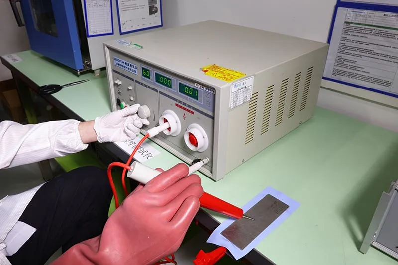
Electrical side
· high dielectric strength supports tight spacing without panic
· verify breakdown voltage after aging, not just fresh samples
Tradeoff handling
· softer blends raise conformity, yet can hurt dielectric strength
· fillers and additives must be picked so material integrity survives flex + heat
Sheen Technology tends to spec this as “bend-friendly insulation,” because that’s what technicians remember on the line.
Factor 4: Minimizing Interface Thermal Resistance to Heat Sinks
Most losses hide at the touchpoints: interface thermal resistance climbs when contact is spotty, and even a great thermal interface material (TIM) can flop if surface contact is uneven. This is where a Flexible phase change thermal conductive film can beat a messy paste, assuming pressure and wetting are matched.
Key knobs that actually move the needle:
· gap filling: enough flow to eliminate voids, not so much it pumps out
· pressure: too low leaves air pockets; too high can squeeze out the TIM layer
· wetting vs. thermal grease behavior: films need controlled softening, greases need containment
| Clamp pressure (kPa) | Bondline thickness (µm) | Interface thermal resistance (K·mm²/W) |
| 50 | 120 | 35 |
| 100 | 90 | 24 |
| 200 | 65 | 16 |
| 300 | 55 | 15 |
Sheen Technology usually frames this as “make the heat sink and TIM act like one part,” because reducing contact hiccups is cheaper than upgrading fans.
Factor 5: Ensuring Lifecycle Performance in Data Centers
In a data center, heat solutions don’t get a vacation; reliability is the whole game, and lifecycle performance means surviving years of load swings without creeping, drying, or cracking. A Flexible phase change thermal conductive film must keep its thermal path stable, even when servers run hot, idle, then spike again.
Aging risks
· thermal degradation in binders slowly raises thermal impedance
· repeated thermal cycling can shift contact quality and pump-out behavior
Material choices that help
· stable organics for long-term stability under continuous soak
· ceramic particles for consistent thermal management without electrical tradeoffs
System fit
· validate with real power electronics profiles, not gentle bench tests
· track operational lifespan metrics: performance after 1k/2k/5k cycles, not just “passes”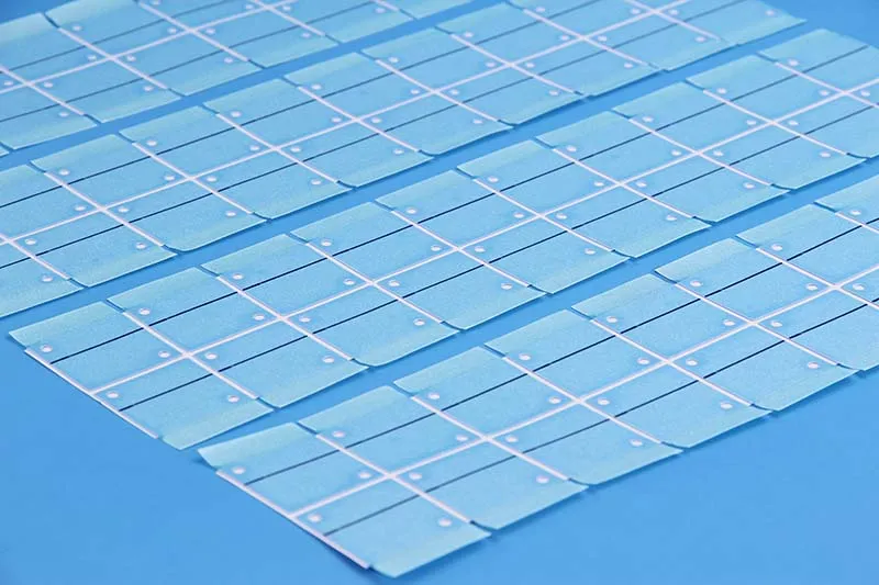
Sheen technology SP205A-60 phase change thermal sheet Reliability Test Report
| Test Items | Test Conditions | Test Equipment |
| High-Temperature Aging | 100℃,1000H | Precision Oven |
| Constant Temperature & Humidity | 85℃、85%RH,1000H | Constant Temperature & Humidity Chamber |
| Thermal Shock | -20℃~80℃,1000H | Constant Temperature & Humidity Chamber |
Criteria for Judging Test Results
| Performance Parameter | Initial Value | Acceptance Criteria |
| Thermal Conductivity(W/m*K) | 6.07 | ±30% |
| Thermal Resistance(℃*in²/W,@10 psi) | 0.082 | ±40% |
| Appearance | Smooth surface, uniform color | No abnormalities (e.g., powdering, discoloration) |
High-Temperature Aging Test Results
| High-Temperature Aging Test Record Sheet | |||||||||
| Aging Time | H | 0 | 200 | 400 | 600 | 800 | 1000 | Change | Assessment |
| Thermal Conductivity | W/m*k | 6.07 | 5.74 | 5.45 | 5.25 | 5.08 | 5.00 | -17.6% | OK |
| Thermal Resistance | ℃*in²/W,@10 psi | 0.082 | 0.084 | 0.089 | 0.095 | 0.102 | 0.107 | +30.5% | OK |
| Appearance | / | No change | No change | No change | No change | Slightly yellow | Slightly yellow | Slightly yellow | OK |
Constant Temperature and Humidity Test Results
| Constant Temperature and Humidity Test Record Sheet | |||||||||
| Aging Time | H | 0 | 200 | 400 | 600 | 800 | 1000 | Change | Assessment |
| Thermal Conductivity | W/m*k | 6.07 | 5.81 | 5.50 | 5.31 | 5.22 | 5.09 | -16.1% | OK |
| Thermal Resistance | ℃*in²/W,@10 psi | 0.082 | 0.090 | 0.094 | 0.098 | 0.101 | 0.105 | +28.0% | OK |
| Appearance | / | No change | No change | No change | No change | Slightly yellow | Slightly yellow | Slightly yellow | OK |
Thermal Shock Test Results
| Thermal Shock Test Record Sheet | |||||||||
| Aging Time | H | 0 | 200 | 400 | 600 | 800 | 1000 | Change | Assessment |
| Thermal Conductivity | W/m*k | 6.07 | 5.72 | 5.50 | 5.33 | 5.18 | 5.07 | -16.5% | OK |
| Thermal Resistance | ℃*in²/W,@10 psi | 0.082 | 0.086 | 0.092 | 0.099 | 0.105 | 0.110 | +34.1% | OK |
| Appearance | / | No change | No change | No change | No change | Slightly yellow | Slightly yellow | Slightly yellow | OK |
Test Conclusion: After aging for 1000 hours under various conditions, the SP205A-60 phase change thermal sheet maintained satisfactory performance with no changes to its appearance. Therefore, the reliability test results are deemed satisfactory.
Need exact thermal conductivity, melting temperature, thickness range, and reliability data before you choose? Download the product datasheets to compare flexible phase change thermal conductive film options.
Sheen Technology treats lifecycle testing like a sanity check: if it can’t survive the boring grind of the rack, it won’t survive anything.
Flexible Film Vs. Heat Pad: Cost Analysis
Data-center teams don’t buy thermal interface materials for fun; they buy them to stop hotspots, cut fan noise, and avoid surprise downtime. This cost view compares a flexible phase change thermal conductive film against traditional pads, with a practical nod to install time, rework pain, and how long performance stays steady—plus how Sheen Technology positions each option.
Flexible Phase Change Thermal Conductive Film
For a Flexible phase change thermal conductive film, the bill looks steep at first, but the math changes once heat and rework enter the chat. This phase change material behaves like a thermal film that hits a softening point under load, improving interface contact so heat transfer stays smooth.
Cost drivers that actually move totals
Materials and assembly
· Higher unit price than a thermal pad, yet lower thermal resistance can trim cooling overhead.
· The conductive path is consistent, so you’re not paying for extra airflow to patch a weak contact.
Integration and service
· Flexibility helps with uneven lids and slight warp, reducing torque “guesswork” during installation.
· Reusability can cut waste when boards get swapped; rework doesn’t always mean a fresh cut piece.
Performance over time
· Stable contact pressure means fewer creeping gaps, so you’re not silently losing performance month by month.
Sheen Technology typically frames flexible phase change thermal conductive film as the pick for high-power SKUs, where a flexible phase change thermal conductive film saves money by avoiding thermal throttling and keeping maintenance boring.
Need a closer match for your project? Browse these related application pages to see where flexible phase change thermal conductive film is used in real systems.
Traditional Heat Pads

Traditional thermal pad choices can be a budget win on day one, especially when you need gap filling and electrical isolation without much fuss. Many are silicone-based, and that softness helps compression, but material thickness and pump-out risk can raise thermal resistance over long runs, nudging fans and chillers to work harder.
Quick cost check in the real world
· Lower purchase cost, faster sourcing, simple cut-and-place.
Where costs sneak back in
· Higher impedance can mean higher heat dissipation demand from the cooling stack.
· Limited recovery after repeated heats can reduce contact quality.
| Item | Typical upfront cost (relative) | Relative thermal resistance impact |
| Flexible phase change thermal conductive film | 1.8 | 0.7 |
| Thin traditional heat pad | 1.0 | 1.0 |
| Thick traditional heat pad | 1.2 | 1.3 |
Practical tip: if you’re using pads as a “catch-all,” test two thicknesses; small changes can swing temps a lot.
Sheen Technology usually positions pads for mixed-height assemblies, but still recommends checking if flexible phase change thermal conductive film fits the hottest chip path.
【Request a Custom Quote】 Not sure which flexible phase change thermal conductive film fits your build? Send us your target operating temperature, thickness target, gap size, and application details, and we can help recommend the right thermal solution for your project.
Sheen Thermal
Dongguan Sheen Electronic Technology Co., Ltd · Founded in 2008
Manufacturer of thermal interface materials and silicone foam for automotive electronics, energy storage, power electronics, communications and consumer electronics.
Certified
- ISO 9001:2015
- ISO 14001:2015
- IATF 16949:2016
What we supply
- Thermal conductivity Up to 90 W/m·K
- Thickness 0.3–10.0 mm
- Custom & samples Die-cut to drawing, 3–7 days