
 English
 usheenthermal

One Thin Sheet, Two Critical Jobs: Heat Transfer and Electrical Isolation
Date:2026-11-06
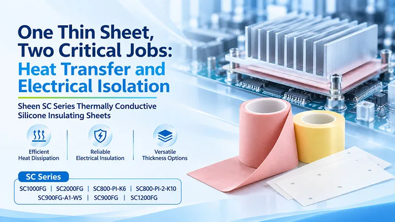
In a switching power supply, industrial drive, or power controller, the thin layer between a device and its heatsink often has two jobs at once. It needs to move heat out. It also needs to keep electrical potentials apart. That sounds simple enough — until thermal resistance, insulation integrity, screw paths, burrs, and clamping conditions all enter the same design review.
Sheen's SC Series of thermally conductive silicone insulating sheets is designed for thin, controlled contact interfaces that need electrical isolation. The family includes PI- and fiberglass-reinforced constructions, multiple thicknesses, and processing options such as roll supply, sheets, die-cutting, and selected adhesive configurations. The seven grades covered here let engineers build a shortlist around thickness, breakdown voltage, area-normalized resistance, and assembly method — then let component-level testing make the final call.
If the thermal budget is tight, start by looking at SC1000FG and SC2000FG. If a thin PI construction matters, compare SC800-PI-K6 with SC800-PI-2-K10. If one-side adhesive would help pre-position the part, ask about the exact SC900FG-A1-W5 configuration. The key is not simply which grade to sample. It is which thickness, reinforcement, adhesive stack, and test condition that sample represents.
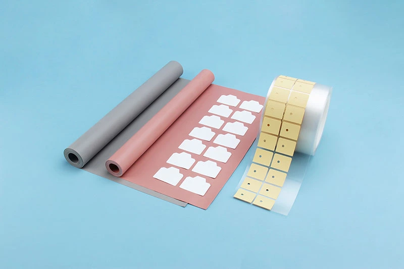
Figure 1. SC800 Series datasheet product image showing roll and sheet forms. Color and appearance are not substitutes for grade identification.
What an Insulating Thermal Pad Actually Does
An insulating thermal pad sits between a heat-generating device and a metal thermal structure. On one hand, it gives heat a more continuous path. On the other, it maintains electrical separation where the device mounting surface and heatsink must not be connected. Some power transistors, rectifiers, and modules have mounting surfaces tied to internal electrodes, while the heatsink may be grounded or shared by several devices. That is where this thin layer earns its keep.
Replace Contact Air Without Adding an Unnecessary Thermal Penalty
Even surfaces that look flat can carry microscopic peaks, valleys, and small air gaps. Under suitable clamping, the insulating thermal sheet conforms to the contact surfaces and replaces part of that air with a thermally conductive material. Actual performance still depends on thickness, surface condition, and contact pressure. The material helps; the joint still has to be built properly.
Break the Electrical Path — Including Screws and Edges
When a device mounting surface is live and the heatsink is grounded or shared, the sheet forms an insulating barrier. But the sheet is only one part of the insulation system. Check screws, bushings, washers, edge clearances, and possible metal paths around the pad. A perfect insulating layer cannot help if a fastener quietly routes electricity around it.
Separate Withstand Voltage From Mechanical Survival
Breakdown voltage and puncture resistance are different evaluations. A breakdown-voltage value does not prove resistance to puncture, cut-through, or tearing. If the assembly has burrs, narrow ligaments, mounting holes, or aggressive screw clamping, evaluate those mechanical risks separately. Material data and component testing support safety design together; neither one alone proves finished-equipment compliance.
Make Placement and Inspection Repeatable
Sheets and rolls can be converted to defined outlines, dimensions, and hole patterns. Suitable adhesive or release-liner arrangements can help with pre-placement in volume assembly. Decide early whether adhesive is needed, because the adhesive layer can affect both total thickness and thermal resistance. Convenience is useful; an unmeasured extra layer is not.
How This Differs From a General Gap-Filler Pad
General thermal pads are often selected primarily to fill larger gaps. Thin insulating thermal sheets place more emphasis on dielectric strength, thickness consistency, and insulation integrity after assembly. Their functions can overlap, so the product name alone does not prove insulation suitability.
Common category constructions include fiberglass reinforcement and polyimide (PI) films. Mica is also used in insulating thermal structures, usually with an interface material to improve contact. Composite sheets may place thermal silicone on one or both sides of an insulating film or reinforcement. These are category-level examples, not a claim that every Sheen SC grade uses the same stack or that the series includes mica-based products.
A traditional mica-plus-grease joint remains a valid option, but coating quantity, spread uniformity, and assembly cleanliness need process control. A preformed insulating thermal sheet fixes thickness, outline, and hole locations in advance. Whether it can replace the incumbent structure still depends on thermal, electrical, and reliability validation. SC materials are best suited to relatively flat, thin-gap interfaces with controlled clamping — not large steps, broad tolerances, or big-gap filling.
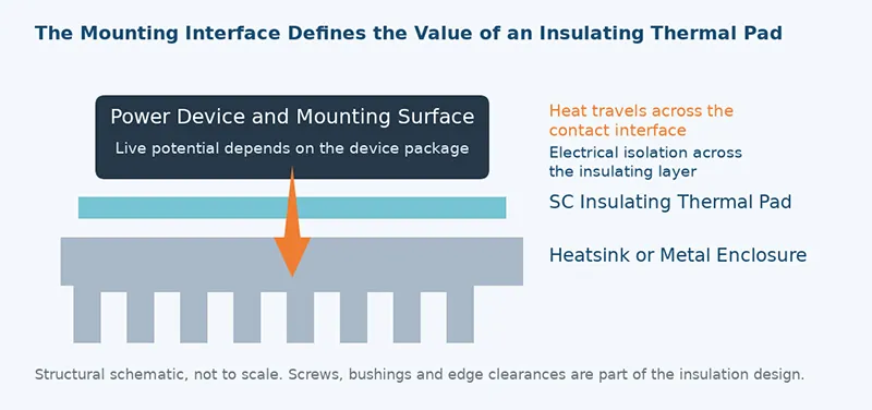
Figure 2. Insulating thermal path between a power device and thermal structure. Insulation integrity belongs to the whole mounting design, not just the sheet.
Where Insulating Thermal Sheets Are Commonly Used
These materials appear most often in power conversion and power-control equipment. MOSFETs, IGBTs, bridge rectifiers, and power modules deserve a close look at both mounting-surface potential and heat-flow path. Whether an external insulating sheet is required depends on the package and equipment structure.
| Product Category | Representative Equipment | Possible Mounting Location |
|---|---|---|
| Power supplies | Switch-mode supplies, fast chargers, charging piles, inverters, UPS systems | Between an isolated switch or rectifier mounting surface and the thermal structure |
| Industrial equipment | Variable-frequency drives, servo drives, welding machines, solar inverters, energy-storage converters | Between a power semiconductor and a metal base, heatsink, or enclosure |
| Automotive electronics | Motor controllers, on-board chargers, selected BMS and power modules | Power-switch or module cooling interfaces that genuinely require external isolation |
| Home appliances | Air conditioners, induction cookers, washing machines | Between power semiconductors in control or drive circuits and their thermal structures |
| Lighting and displays | LED lighting and display equipment | Between a heat-generating mounting surface requiring isolation and a metal thermal structure |
| Computing, communications and control | Server PSUs, telecom power supplies, selected high-power control boards | Power-device or other cooling surfaces that require electrical isolation |
Table 1. Common application categories for insulating thermal sheets. Not every product needs an external sheet, and this table does not imply industry-specific certification for every SC grade.
Start With Electrical Requirements, Then Check Thermal and Structural Fit
Begin with working voltage, AC or DC conditions, required withstand voltage, and the insulation objective. Then compare thermal conductivity where available, area-normalized resistance for the actual configuration, total thickness, tolerance, allowed compression, contact pressure, and surface flatness. Conductivity describes material-level heat transfer; assembled behavior also depends on thickness and contact. A good conductivity headline cannot settle the design by itself.
The SC datasheets reviewed here do not provide compression specifications. Do not infer compression rate from Shore A hardness. If a device mounting surface is live and a metal heatsink is grounded, the insulation design may call for a suitable insulating thermal material or another insulating structure. Base that decision on mounting-surface potential and the package's own insulation. Live pins alone do not prove that the case or thermal tab is live. For packages with insulated bases, first confirm whether an additional layer is necessary at all.
Seven SC Grades at a Glance
This comparison covers all seven grades found in the five datasheets reviewed. The table prioritizes the values most useful for first-pass screening: thickness, AC breakdown voltage, and area-normalized thermal resistance. Original upper- and lower-limit meanings are retained.
| Grade | Color | Thickness Range, mm | Breakdown Voltage, kV AC | Area Resistance, °C·in²/W @50 psi | Initial Evaluation Direction |
|---|---|---|---|---|---|
| SC800-PI-K6 | Gray | 0.12–0.25 | ≥6 | ≤1.0 | Thin construction with a higher breakdown-voltage specification |
| SC800-PI-2-K10 | Yellow | 0.13–0.17 | ≥4 | ≤0.5 | Thin insulation with closer resistance control |
| SC800FG | Gray | 0.23–0.30 | ≥4 | ≤0.7 | General thin insulating thermal interface |
| SC900FG | Pink | 0.25–0.50 | ≥6 | ≤0.8 | Higher breakdown-voltage specification and assembly fit |
| SC900FG-A1-W5 | Pink | 0.25–0.50 | ≥6 | ≤0.85 | Candidate where one-side adhesive positioning is needed |
| SC1000FG | White | 0.20–0.50 | ≥5 | ≤0.3 | Low resistance combined with tensile-strength requirements |
| SC2000FG | White and green | 0.20–0.50 | ≥5 | ≤0.2 | Low-resistance evaluation for tighter thermal budgets |
Table 2. Test methods: thickness ASTM D374; breakdown voltage ASTM D149; area-normalized thermal resistance ASTM D5470. Source documents: Version 20260327 V1.
Shared listed properties include Shore A hardness of 85–95, an operating range of −40 to 150 °C, UL 94 V-0 flammability, dielectric constant ≤5 at 1 MHz, and RoHS, Halogen, and REACH marked PASS. Verify the valid report scope for the exact grade, thickness, and formulation. The current datasheets do not list thermal conductivity for these grades, so older W/m·K graphics should not be treated as current specifications. For thin insulating interfaces, the stated configuration and pressure-specific area resistance are the more useful starting point.
Keep the Datasheet, Quote and Sample on the Same Configuration
Once a grade is shortlisted, freeze what the sample actually is. Changes in thickness, reinforcement, or adhesive can change thermal performance, electrical behavior, and converting results. When requesting samples, align the full grade name, specification revision, total thickness and tolerance, reinforcement, adhesive stack, and tested specimen configuration. Series-level data should not be casually applied to every custom part.
For example, when evaluating SC1000FG's ≤0.3 °C·in²/W specification, confirm that it corresponds to the 0.23 mm configuration in the table header, then confirm adhesive state, test temperature, and measurement conditions. If the sample changes thickness or adhesive, request data for that configuration. The SC900FG header-versus-range discrepancy needs Sheen's confirmation before sample preparation; this article does not silently reconcile the two values.
Keep a configuration record for every sample and tie it to the datasheet, quotation line, drawing, and test report. Record later changes to thickness, adhesive, or converted shape so retesting and production approval remain traceable.
Lower Resistance Still Needs the Right Converting and Assembly Conditions
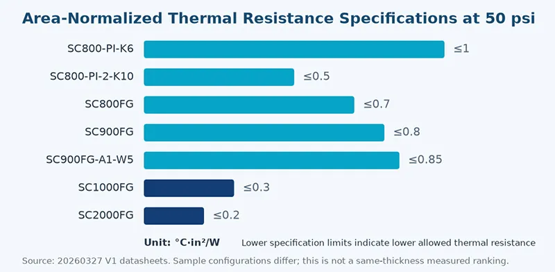
Figure 3. Area-resistance upper limits in each grade's own datasheet configuration. PI grades use 0.15 mm headers; SC800FG uses 0.23 mm; SC1000FG and SC2000FG use 0.23 mm.
For low-resistance candidates, SC1000FG and SC2000FG are boron nitride insulating sheets with listed area-resistance limits of ≤0.3 and ≤0.2 °C·in²/W at 50 psi, respectively. Both list AC breakdown voltage ≥5 kV. They deserve sample evaluation where the interface budget is tight, but their tensile-strength lower limits differ. Resistance alone should not dictate the converting structure.
For thin constructions, SC800-PI-K6 spans 0.12–0.25 mm with AC breakdown voltage ≥6 kV, while SC800-PI-2-K10 spans 0.13–0.17 mm with area resistance ≤0.5 °C·in²/W. They represent different electrical, thermal, and thickness combinations. For placement and process needs, SC900FG and SC900FG-A1-W5 both list ≥6 kV AC breakdown voltage. One-side adhesive can help pre-positioning, but adhesive thickness, resistance, and liner removal still belong in validation. Adhesive is an assembly option, not an automatic performance upgrade.
| Grade | Density, g/cm³ | Tensile Strength, MPa | Maximum Elongation, % | Volume Resistivity, Ω·cm |
|---|---|---|---|---|
| SC800-PI-K6 | 2.2 ± 0.2 | ≥20 | ≥20 | ≥10¹⁴ |
| SC800-PI-2-K10 | 1.8 ± 0.3 | ≥12 | ≥5 | ≥10¹⁴ |
| SC800FG | 1.8 ± 0.3 | ≥8 | ≥1 | ≥10¹⁴ |
| SC900FG | 1.80 ± 0.2 | ≥15 | ≥0.2 | ≥10¹⁴ |
| SC900FG-A1-W5 | 1.80 ± 0.2 | ≥20 | ≥0.5 | ≥10¹⁴ |
| SC1000FG | 1.80 ± 0.2 | ≥40 | ≥2 | ≥10¹³ |
| SC2000FG | 1.70 ± 0.2 | ≥15 | ≥2 | ≥10¹³ |
Table 3. Density: ASTM D792. Tensile strength and maximum elongation: ASTM D412, using the datasheet field names.
Use Area-Normalized Resistance as a Thermal Design Tool
The temperature rise contributed by an insulating sheet relates to heat flux and actual interface resistance. A useful engineering approximation is:
ΔT ≈ q″ × R″ — where q″ is heat flux in W/cm² and R″ is area-normalized resistance in °C·cm²/W.
The unit conversion is 1 °C·in²/W = 6.4516 °C·cm²/W. Thus 0.2, 0.3, and 0.8 °C·in²/W correspond to approximately 1.29, 1.94, and 5.16 °C·cm²/W. At a purely assumed heat flux of 5 W/cm², if the actual interfaces happened to achieve those values, the associated temperature differences would be about 6.5, 9.7, and 25.8 °C.
That is a hypothetical unit-and-design illustration, not a measured SC temperature result or a finished-system prediction. It ignores heat spreading, nonuniform contact, and parallel heat paths. Do not turn specification upper limits directly into promised system cooling gains.
Use Data at the Real Pressure and Configuration
The stated 50 psi is approximately 0.345 MPa. It is a test pressure, not a recommended assembly pressure for every device. Contact condition affects interface heat transfer, and industry selection guidance treats clamping pressure as a major variable. If actual pressure is lower or the heatsink is warped, request pressure-versus-resistance data for the target configuration and retest in the real fixture. Screw torque is not contact pressure; contact area and structural stiffness sit between them.
The reviewed SC datasheets provide 50 psi resistance specifications but no complete pressure curves or batch-scatter data. For conditions outside the documents, confirm available reports or additional testing with Sheen, then verify on the actual component. A single point cannot be extrapolated into a full curve — tempting shortcut, wrong graph.
Evaluate Adhesive Samples as the Final Layer Stack
Adhesive can assist placement, but it changes the interface. For candidates such as SC900FG-A1-W5, confirm whether the resistance value includes the final adhesive layer, whether total thickness includes it, and what remains after liner removal. Extra coating, one-side adhesive, and two-side adhesive should not automatically share one resistance dataset. Test reports should also make clear whether the value describes the complete contact stack or a treated material-body result.
Likewise, material breakdown voltage is an electrical result for a defined specimen and test condition. It is not the equipment's allowable continuous working voltage. Edge creepage, air clearance, screw paths, temperature, humidity, and aging all influence the final insulation result. A material test never replaces finished-equipment safety design.
Put the Material in the Right Mounting Location
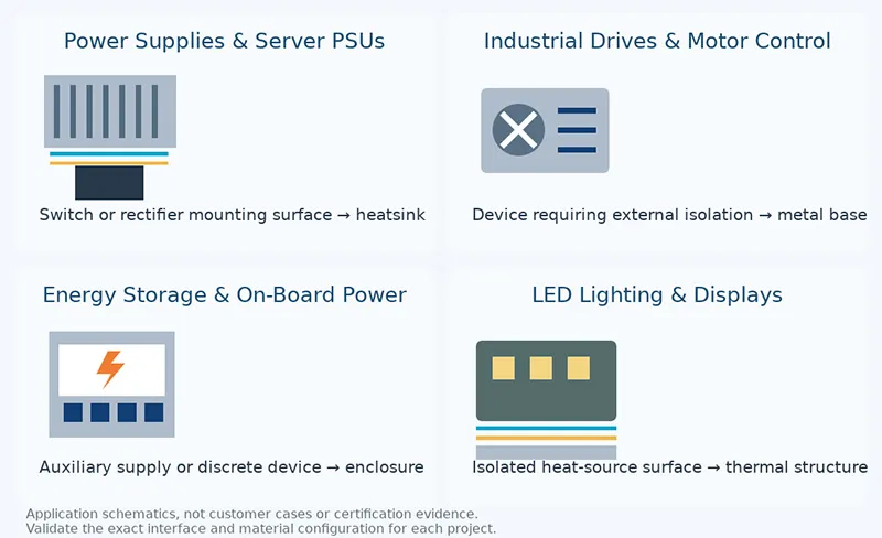
Figure 4. Four candidate application interfaces. These schematics show possible mounting locations, not completed system certifications or production qualifications.
Switch-Mode Power Supplies and Server PSUs

Figure 5. Application illustration for power-supply and power-device mounting interfaces. Validate the exact package and insulation requirement.
Inside AC-DC, DC-DC, and server power supplies, some switches, rectifiers, and power devices transfer heat into a metal heatsink. Where the device mounting surface must be isolated from that structure, SC materials can be evaluated as the insulating thermal interface.
A practical shortlist might start with SC800FG for a conventional interface, SC900FG where a higher breakdown-voltage specification is desired, and SC1000FG or SC2000FG for a tighter thermal budget. Check whether the device already has an insulated package, plus clamping method and hole-edge margin. In AI servers, the relevant SC opportunities are primarily in power supplies and suitable power-device interfaces — not automatically between a bare GPU die and a cold plate.
Industrial Drives and Air-Conditioner Compressor Control
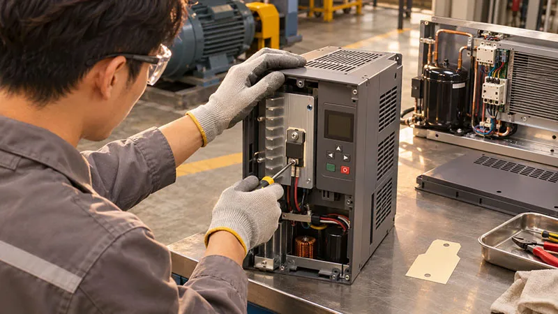
Figure 6. Application illustration for industrial power-control assemblies. Confirm flatness, burrs, vibration, and insulation after thermal cycling.
In industrial drives, variable-frequency controls, and compressor-control boards, power devices often mount to aluminum bases, heatsinks, or cast-aluminum housings. Sheen's earlier application-sharing material also showed the concept of an AC-DC control module coupled to a cast-aluminum thermal part through an insulating sheet.
Where an external insulating layer is genuinely needed, compare the thin dimensions of SC800-PI-2-K10 with the low-resistance specifications of SC1000FG and SC2000FG. Whether a module with an insulated base needs another sheet is a system decision; avoid adding resistance without a purpose. Inspect casting flatness, hole burrs, vibration, and insulation integrity after thermal cycling.
Energy Storage and On-Board Power
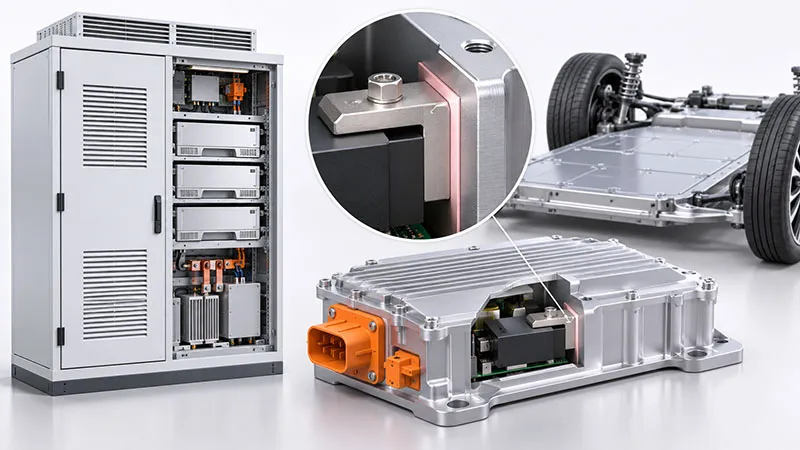
Figure 7. Application illustration for energy-storage and vehicle-power interfaces. This does not represent automotive qualification or high-voltage system approval.
Auxiliary supplies, selected discrete power devices, and mounting surfaces requiring potential isolation in energy-storage converters and on-board power systems can be project-evaluation directions for SC materials. Where the thermal budget is tight and controlled clamping is available, compare SC1000FG with SC2000FG. Where one-side pre-placement is useful, evaluate SC900FG-A1-W5.
These are engineering suggestions based on interface function, not proof of automotive qualification or high-voltage suitability. Confirm that actual hotspots remain within the material's confirmed range, then validate withstand voltage, temperature and humidity, thermal cycling, vibration, and life as required. These sheets are not a substitute for large-gap battery-pack fillers or thermal-runaway barrier materials.
LED Lighting and Display Equipment

Figure 8. Application illustration for LED and display power-device interfaces. Verify whether an additional insulating layer is necessary.
Power devices, semiconductor thermal assemblies, and selected mounting interfaces in LED lighting and displays can be evaluated for insulating thermal sheets. The source datasheets list LED lighting and LCD-type display equipment among typical applications.
Where mounting-surface isolation is clearly required, compare SC800 grades, SC900FG, or the lower-resistance SC1000FG and SC2000FG according to thickness, temperature-rise budget, and placement process. If a metal-core board's dielectric layer already provides the required isolation, first decide whether another sheet is needed. For large contact areas, verify flatness and the real pressure distribution.
Move From Sample Properties to Assembled Reliability
For an electrically isolated thermal interface, initial resistance and material breakdown voltage are only the start. Whether the thin sheet remains intact after die-cutting, liner removal, screw clamping, and long-term operation directly affects assembly insulation. Build a validation plan around actual duty conditions, then check whether existing reports really cover them.
| Validation Item | Conditions to Fix or State | Results to Record |
|---|---|---|
| Assembly integrity | Target outline, holes, clamping method, and actual thermal surface | Damage, wrinkles, hole-edge integrity and insulation coverage after liner removal or assembly; puncture or cut-through evaluation where needed |
| Thermal performance and contact stability | Ambient, power, airflow or cooling conditions, and temperature locations | Steady-state temperature rise, pressure condition and sample configuration; identical boundaries for the control |
| Electrical insulation | Project-required component withstand and insulation-resistance conditions | Test voltage, AC/DC, duration, leakage criterion and environment; inspect screw and edge paths |
| Retention after aging | Thermal cycling, damp heat, vibration, sustained clamping, or other duty-relevant exposures | Before/after resistance or temperature rise, insulation resistance, withstand result, appearance, and sample count |
Table 4. Recommended project validation items, not a list of tests Sheen has already completed.
Check Whether an Existing Report Fits Your Project
When requesting samples, ask whether reports exist for the same formulation, thickness, and adhesive construction under thermal cycling, damp heat, sustained clamping, or other relevant exposures. Read specimen configuration, conditions, sample count, and before/after change — not just the word PASS. Where target-condition data is missing, define additional testing or arrange component-level validation.
Make Application Cases Reviewable
A useful selection case identifies the device or module, material location, power, contact area, thickness and adhesive, clamping method, ambient and cooling conditions, temperature locations, control material, results, and sample count. That is what lets another engineer judge comparability. For SC1000FG versus SC2000FG, use the same assembly, nominal thickness, adhesive state, and allowable clamping condition, while recording actual specimen thickness. Choose using steady-state temperature rise, assembly integrity, and post-aging change once electrical isolation is satisfied. No reviewable component comparison was included in the source package, so the resistance-conversion example here is not evidence of actual cooling improvement.
From Roll Stock to Stable Production
The SC documents list rolls, sheets, and custom die-cutting. SC800, SC900FG, and SC900FG-A1-W5 list 300 mm × 50 m rolls; SC1000FG and SC2000FG list 305 mm × 305 mm sheets. Confirm available converting formats for the required configuration. Reinforcement, adhesive, and tack options depend on grade and construction.
For production, confirm outline, locating holes, and release method together with material performance. Inspect narrow regions and hole edges on complex parts. Avoid wrinkles and tensile distortion after liner removal, and remove burrs and particles before placement. After assembly, verify effective insulation coverage — especially around screws, device edges, and metal housings.
For replacement of mica-plus-grease or another brand's insulating sheet, compare the same dimensions, nominal thickness, adhesive state, and assembly conditions. Record steady-state temperature rise, assembly efficiency, yield, and post-aging behavior before calculating total material and converting cost.
Recommended Project Sequence
- Define the interface: device model, mounting-surface potential, heatsink structure, and insulation objective.
- Freeze the configuration: total thickness, reinforcement, adhesive, outline, holes, and actual clamping conditions.
- Validate thermal performance: record temperature rise at target power, ambient, and mounting pressure; compare candidate configurations.
- Validate electrical and mechanical performance: component withstand, insulation resistance, hole edges, screw paths, and required aging.
- Freeze the production specification: material revision, drawing, tolerances, inspection conditions, packaging, and traceability in the approval package.
Request Samples by Configuration, Not Just by Grade Name
If you are selecting an insulating thermal material for a power supply, industrial controller, LED product, or another power-electronics project, start with the target interface and test requirements. A useful sample request answers two questions: which grade, and which thickness, adhesive, and construction should be tested?
For low-resistance interfaces, ask about SC1000FG and SC2000FG. For thin PI constructions, compare SC800-PI-K6 and SC800-PI-2-K10. For rolls, die-cutting, or one-side adhesive positioning, confirm suitable configurations of SC800FG, SC900FG, and SC900FG-A1-W5.
| Discussion Item | Information to Provide Sheen | Confirm With the Request |
|---|---|---|
| Application and electrical requirements | Device model, mounting-surface potential, working voltage, component withstand target, insulation objective | Candidate fit and available electrical data or reports |
| Thermal and structural conditions | Power, contact area, target thickness, ambient, allowable clamping conditions | Candidate thickness, adhesive stack, and thermal data for the corresponding configuration and pressure |
| Sample converting | Quantity, sample dimensions or die-cut drawing, holes, adhesive and placement needs | Available sample form, dimensions and tolerances; whether custom converting is required |
| Cost and timing | Delivery address, required test window, and whether standard coupons are acceptable | Sample and converting charges, freight responsibility, preparation time and shipment arrangement |
| Production introduction | Validation plan, estimated volume, and intended material configuration | Available test and compliance documents, configuration traceability and production supply conditions |
Table 5. Listed roll and sheet dimensions describe product supply forms, not guaranteed sample dimensions.
【Request a Custom Quote】A clear request might read: ‘We plan to compare SC1000FG and SC2000FG for an electrically isolated power-device interface. Please review the mounting drawing, recommend suitable thickness and adhesive configurations, and provide the corresponding datasheets and available test reports. Please also confirm sample dimensions, quantity, cost, and preparation time.
Start with defined samples. Validate thermal, electrical, and assembly performance in your own structure. Then turn the result into a controlled production specification.
Sheen Thermal
Dongguan Sheen Electronic Technology Co., Ltd · Founded in 2008
Manufacturer of thermal interface materials and silicone foam for automotive electronics, energy storage, power electronics, communications and consumer electronics.
Certified
- ISO 9001:2015
- ISO 14001:2015
- IATF 16949:2016
What we supply
- Thermal conductivity Up to 90 W/m·K
- Thickness 0.3–10.0 mm
- Custom & samples Die-cut to drawing, 3–7 days