
 English
 usheenthermal

Stable Test Temperatures Start With One Thin Layer: Sheen SG560 Thermal Grease for Chip and Module Testing
Date:2026-11-06
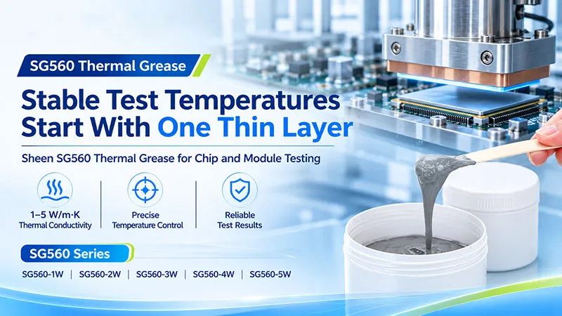
The test program is running. Load ramps up, and the DUT temperature climbs with it. The thermal head says it has reached setpoint — but has the chip actually made it to temperature? And why does the same sample produce a different temperature curve the moment you re-mount it?
If you work in chip or module testing, these details send you straight back to that unglamorous layer between the device and the thermal head.
Here's the thing: a test station doesn't need to be “colder.” It needs the device to sit inside a specified temperature window while running a specified load. Whether heat can get out in time, and whether contact is rebuilt the same way every cycle, directly shapes how you interpret both temperature control and test results. Thermal grease is one link in that heat path worth choosing deliberately.
Sheen's SG560 series offers six thermal greases from 1 to 5 W/m·K. This article walks through packaged-chip testing, loaded compute-module testing, power-module testing, and the fixed thermal interfaces inside test equipment — moving from datasheet parameters to station-level verification.

Figure 1. Sheen SG series products and a general dispensing illustration. This image is not a photo of a chip-test station and does not represent a specified dispensing volume.
When the DUT Runs Hot, Check the Interface Before You Blame the Program
SG560's thin-layer thermal performance makes it a candidate for interfaces that allow grease, have mechanical clamping, and can be kept clean. Whether it fits a specific test position still has to be verified together — thermal resistance, clamping, residue, and maintenance. The scenarios here are engineering-evaluation directions, not completed equipment qualifications.
The real material question at a test station is not “can heat get out” but “can heat get out the same way, every single contact.” That's the gap this article tries to close.
Even “Flat” Metal Makes Heat Take the Long Way Around
A metal surface that looks flat to the eye still has microscopic peaks and valleys. Press two surfaces together and the actual contact area never fills the whole interface. The rest? Air. And air sits exactly where heat most needs a clear road.
Thermal grease is typically a matrix filled with thermally conductive particles plus suitable additives. As a paste, it spreads into those microscopic voids, improving wetting and contact, and lowering the interface's resistance to heat flow. Its job is the thin interface; the heatsink still has to carry the heat away by forced air or liquid cooling.
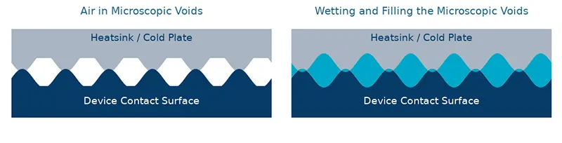
Figure 2. Contact-interface schematic: microscopic voids versus grease wetting and filling. Not a real micrograph; proportions are illustrative.
Conductivity Sets How Well Heat Moves — Thickness Sets How Far It Travels
Two numbers do most of the work here. Treat thermal conductivity k as one indicator of how well the material moves heat. Treat the assembled bond-line thickness (BLT) as how far heat has to travel through it. A one-dimensional approximation of bulk resistance is R = t/(kA); a real interface adds contact resistance on both sides. So comparing W/m·K alone cannot decide which build runs cooler.
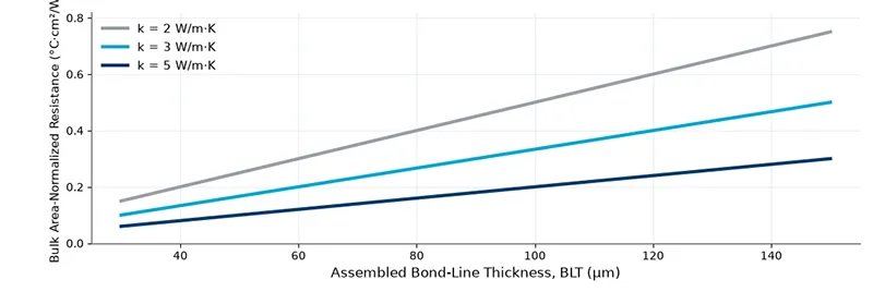
Figure 3. Theoretical relationship: bulk area resistance R″ = t/k. Material body only, contact resistance not included. Not measured SG560 data.
Example: two 5 W/m·K layers, one at 100 μm and one at 50 μm — in the ideal model, the thinner layer's bulk resistance is half. But if aggressive dispensing leaves local starved spots, voids, or can no longer compensate package warpage, contact resistance can go up instead. The value of “thin” only exists when contact is full, coverage is effective, and the structure allows it. And pressure always answers to the device and assembly limits, not the other way around.
Six Grades, One Table: Let the Specs Narrow the Field
SG560-10, SG560-20, SG560-30, SG560-40, SG560-50, and SG560-50-58 form a 1-to-5 W/m·K selection. The comparison below uses a single datasheet revision (20260117V0) throughout, so you're not mixing numbers from different versions or test pressures.
| Grade | Thermal Conductivity, W/m·K | Thermal Resistance Ceiling, °C·in²/W | Minimum Interface Thickness, mm | Color |
|---|---|---|---|---|
| SG560-10 | 1.0 ± 0.1 | ≤0.15 | 0.06 | White |
| SG560-20 | 2.0 ± 0.2 | ≤0.045 | 0.05 | White |
| SG560-30 | 3.0 ± 0.3 | ≤0.03 | 0.05 | Gray |
| SG560-40 | 4.0 ± 0.4 | ≤0.02 | 0.05 | Gray |
| SG560-50 | 5.0 ± 0.5 | ≤0.016 | 0.05 | Gray |
| SG560-50-58 | 5.0 ± 0.5 | ≤0.014 | 0.03 | Gray |
Table 1. Thermal conductivity and thermal resistance test standard: ASTM D5470; resistance condition: @50 psi (approx. 345 kPa).
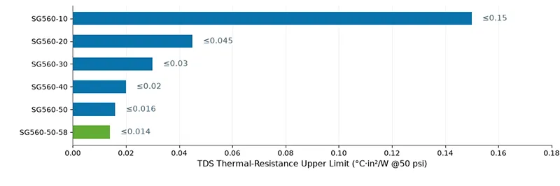
Figure 4. Datasheet thermal-resistance upper limits across the six grades. Bar length is a specification ceiling, not a same-bench measurement;
Turning the Table Into a Shortlist
For fixed contact interfaces inside test equipment, where thermal headroom is relatively generous, SG560-10 and SG560-20 are reasonable first-pass candidates. For the thin layers in loaded module-test interfaces, put SG560-30 and SG560-40 into the comparison. Where the resistance budget is tight and the structure allows thin clamped layers, focus on SG560-50 versus SG560-50-58.
This is a thermal-budget screening path, not a one-to-one binding between grade and power class. Two devices with the same name can differ completely in contact area, heat flux, assembly pressure, and lifetime targets. The final answer comes from sample validation — as it should.
Same 5 W/m·K, Different Thin-Layer Story: SG560-50 vs SG560-50-58
SG560-50 and SG560-50-58 both list 5.0 ± 0.5 W/m·K. Fixate on that single number and you'll miss what makes the -58 variant interesting for thin interfaces.
| Comparison Item | SG560-50 | SG560-50-58 |
|---|---|---|
| Thermal conductivity, W/m·K | 5.0 ± 0.5 | 5.0 ± 0.5 |
| Thermal resistance, °C·in²/W @50 psi | ≤0.016 | ≤0.014 |
| Minimum interface thickness, mm | 0.05 | 0.03 |
| Cone penetration, 0.1 mm @25°C | 330 ± 20 | 320 ± 20 |
| Density, g/cm³ | 2.5 ± 0.2 | 2.6 ± 0.2 |
Table 2. Datasheet line-item comparison of the two 5 W/m·K grades. Cone penetration: GB/T 269. Density: ASTM D792.
SG560-50-58 lists a minimum interface thickness of 0.03 mm (30 μm) versus 0.05 mm (50 μm) for SG560-50. For structures that allow grease — a thermal head against a packaged lid, or a module's metal contact surface — if flatness, assembly pressure, and dispensing control support a thinner layer, SG560-50-58 deserves a slot in the sample comparison.
On paper, 0.03 mm is 40% smaller than 0.05 mm, and the resistance ceiling drops 12.5% from 0.016 to 0.014. Those are two separate datasheet line items — not a measured cause-and-effect pair, and definitely not a 12.5% device-temperature drop. Say it plainly: the specs travel separately.
On the Production Line, Rheology and Dosage Still Have to Pass
| Grade | Cone Penetration, 0.1 mm @25°C | Density, g/cm³ |
|---|---|---|
| SG560-10 | 400 ± 20 | 2.2 ± 0.2 |
| SG560-20 | 360 ± 20 | 2.85 ± 0.2 |
| SG560-30 | 360 ± 20 | 2.6 ± 0.2 |
| SG560-40 | 330 ± 20 | 2.4 ± 0.2 |
Table 3. Process-relevant parameters for the remaining four grades. Cone penetration cannot be converted directly into viscosity or dispensing speed.
Cone penetration helps compare consistency under defined conditions, but the same equipment pressure does not guarantee the same discharge volume across different materials. Density matters too: switch grades, and even with the same weigh setting, the delivered volume changes. Needles, stencils, dispensing paths, and weight windows all need re-qualification with the new material.
The selection table narrows the field. The real answer comes from comparing candidates in the same assembly structure and the same test conditions.
Chip Test: Bring the Thermal Contact Into the Temperature-Control Loop
Final test (FT), system-level test (SLT), and related engineering validation of packaged chips all need device temperature managed under electrical load. Cohu's published active thermal control material, for example, uses device temperature or power feedback for test-site temperature control. The takeaway: the thermal head's setpoint, the contact surface temperature, and the chip junction temperature are different quantities that need to be correlated, not conflated.
Under Load Steps, “It's Touching” Is Not the Same as “It's Working”
Picture a station: the packaged chip enters the socket, the thermal head clamps down, and the program switches from idle to high load. Chip self-heating jumps, and that heat now has to cross the package and the contact interface into the thermal head. If the interface is starved, too thick, or clamped unevenly, the temperature-control system can be working perfectly while the DUT still shows larger excursions or longer stabilization waits.
For packaged lid surfaces where the equipment vendor allows grease, dosage is controllable, and a cleaning process exists, SG560 can be tested as a candidate TIM. The point is not “it runs cooler with grease.” The point is comparing DUT temperature deviation, peak overshoot, stabilization time, and re-mount variation under the same load sequence. Those are validation targets, not existing SG560 performance claims.
| Chip-Test Stage | Candidate Contact Location | Question the Station Must Answer |
|---|---|---|
| Engineering debug and characterization | Package lid to thermal head or cold plate | How far is actual temperature from setpoint? |
| FT / SLT loaded stations | Grease-allowed DUT thermal contact surfaces | How long to enter the temperature window after a load step? |
| Multi-site parallel testing | Each site's own thermal contact interface | Is the site-to-site spread stable at equal power? |
| Internal assembly of temperature-control modules | Fixed interfaces such as heat spreader to cold plate | Is interface resistance repeatable before and after maintenance? |
Table 4. Candidate interfaces and validation tasks for chip testing. The equipment vendor must confirm specific structures; electrical contact regions are not grease locations.
Turning Thin-Layer Potential Into Measurable Contact Consistency
With a tight resistance budget, compare SG560-40, SG560-50, and SG560-50-58 head to head. SG560-50-58's listed 30 μm minimum interface thickness is a screening clue for thin-layer builds — but at stations with warpage, lid tilt, or mechanical limits, do not assume every mount reaches it.
Use a representative package or a proven thermal test vehicle to confirm clamping and spread first, then move to real DUTs. For bare die, evaluate edge damage, load, surface compatibility, and residue removal separately; a lid package's dispensing recipe does not transfer automatically.
The end point of chip-test selection is how the DUT performs under specified load and temperature window. W/m·K is just where the conversation starts.
Module Test: Give Loaded Temperatures a Repeatable Set of Conditions
Module testing amplifies every interface issue: more devices, more scattered hotspots, and module lids or baseplates that may vary in flatness. Two mounts under the same program with different contact produce different temperature curves. Define the thermal boundary first, then talk materials.
Compute Modules and Board-Level SLT
For compute modules with metal lids, thermal bases, or provisions for an external cold plate, evaluate a thin-layer scheme between the specified thermal contact surface and the test cold plate. While the program runs matrix operations, data transfers, or other representative loads, track the main chip's hotspot temperature, power, and time-to-stabilization — and record the clamping conditions of the contact.
On grease-allowed thin interfaces, SG560-30 and SG560-40 work as comparison candidates; tighten the budget further and add SG560-50 and SG560-50-58. If several devices of different heights share one cold plate inside the module, verify each gap separately — a large height difference is not something you compensate for by simply piling on more grease.
Power Module Testing
Loaded evaluation of IGBT and SiC power modules can involve contact between the module baseplate and a cold plate. Where the module's and the machine's insulation schemes allow it, SG560 can be a candidate for that thin interface — but note: the six SG560 datasheets provide no dielectric strength or volume resistivity. Do not assign the grease an unverified electrical-insulation job.
During power cycling, thermal resistance, or lifetime evaluation, the TIM itself is part of the test boundary. Changing grease, thickness, or clamping changes the temperature response. For tests that study degradation of the device under test, fix and record the TIM plan. Lower resistance does not automatically mean a more valid test — and never quietly alter the specified stress.
Communication Module Testing
For comms modules with metal housings, evaluate the housing-to-fixture-cold-plate material scheme at loaded stations where housing contact is allowed. When measuring bit error, power, or other metrics, record module temperature at the same time; if the thermal boundary changes, the comparability of before/after data needs re-examination.
Where optical end faces, sensitive contacts, or silicone-restricted specifications are involved, confirm contamination compatibility first. Grease allowed outside the test fixture does not mean grease allowed inside the module. And for stations with frequent insertion cycles and no-residue requirements, cleaning time and residue control become material screening criteria in their own right.
The more complex the module, the more you need the heat path drawn out first: which surface contacts, how much heat moves, what pressure is allowed, and which zones must stay clean.
High-Traffic Interfaces: Fixed Joints and DUT-Contact Joints Are Different Animals
Test fixtures contain two very different kinds of interface. One is fixed long-term — say, between a heat spreader and a cold plate. The other opens and closes every time a DUT comes in or out. Both need heat transfer; the selection logic is not the same.
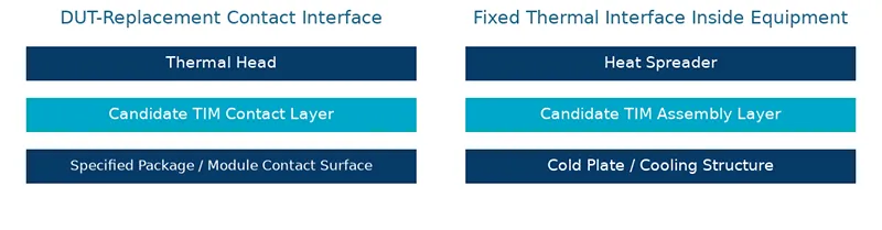
Figure 5. Candidate thermal interfaces in test equipment — schematic, not an installed SG560 case. Every evaluable position must satisfy the equipment's material specification.
Build Separate Verification Methods for Each
For fixed interfaces, focus on initial resistance, drift after cycling, and recovery after disassembly maintenance. For repeated DUT-contact interfaces, also record where material transfers, whether the interface starves after opening, whether the next clamp restores coverage, and how much labor cleaning consumes. Cohu's test-TIM material likewise lists repeatability, residue cleanup, and refurbishment as the concerns to manage.
The current SG560 datasheets contain no data on repeated-contact counts, transfer residue, cleaning cadence, or pump-out cycles. So position it as a to-be-verified candidate for grease-allowed stations — not as “ten-thousand reuses,” “cleaning-free,” or “suited to every high-speed handler.” For stations that must run dry contact, evaluate other TIM options with verification behind them.
Wafer Test: Don't Transplant the Package Recipe
Wafer-level testing relies on the wafer, the chuck, and the probe system working together. FormFactor's published thermal chuck material emphasizes vacuum hold, flatness, and electrical test performance together — meaning the thermal interface is constrained by electrical and mechanical design at the same time.
That is not a recommendation to apply SG560 to wafer backsides, vacuum holes, probes, pads, or electrical contact regions. The discussion to have with the equipment vendor first is about internal, grease-allowed, fixed thermal connections isolated from measurement and vacuum zones — for example, the mounting face between a dedicated heat spreader and the cooling structure. Compatibility still needs item-by-item confirmation.
In this industry, where the material goes matters just as much as how conductive it is. Confirm the position first; decide on sampling second.
From Sample to Station: Validate Every Thermal Contact
One good-looking temperature curve is not enough to switch materials at a station. The same material can respond differently when surface cleanliness, dosage, clamping force, or repeat-contact state changes. Tie the material trial into machine calibration, the test program, and the maintenance process.
Step 1: Get the Contact Surfaces Clean
Follow the cleaning process allowed for the device and heatsink: remove oils, old material, and particles; use suitable lint-free wipes; and confirm the solvent has fully flashed off. Debris raises local gaps, and leftover contamination can block wetting.
Step 2: Define the Pattern Before the Volume
Choose stencil printing, squeegee coating, or a validated dot pattern based on device area and layout. At test stations, confirm equipment-material compatibility and set a single-dose volume, pattern location, wait time, top-up criteria, and cleaning frequency. The judgment that matters is effective coverage and edge overflow after assembly — not whether it “looks thick enough” before clamping.
The 70–80% printed-area figure from the original application material can serve as a starting reference for specific structures. It describes the pre-assembly pattern — it is not a universal final-coverage standard for every device. The actual pattern must account for clamped spread, heat-source layout, venting paths, and keep-out zones.
Step 3: Separate Stencil Thickness From Assembled Thickness
The 0.08–0.12 mm stencil-tooling thickness in the application material is a dispensing-process reference. The 0.03–0.06 mm minimum interface thickness in the datasheets is a different kind of line item. Stencil openings, transfer efficiency, dosage, flatness, and clamping conditions jointly decide the final BLT — no direct equals sign between the two numbers.
Step 4: Clamp Evenly, Then Verify by Teardown and Temperature
Assemble in the sequence, torque, and load specified for the device and thermal structure, and avoid one-sided lift. The 50 psi behind the datasheet resistance is a test condition — not a lock-down instruction that applies to every CPU or power module. Teardown samples to inspect spread and starved areas, and hold the program, power sequence, cooling conditions, measurement locations, and clamping load fixed while comparing DUT temperatures. Confirm with the equipment vendor how “device at temperature” is actually judged.
| Stage | Validation Records Worth Keeping |
|---|---|
| Initial contact | Dosage, clamping force, coverage, BLT or structural gap |
| Load change | DUT temperature deviation, peak overshoot, time to enter the temperature window |
| Repeated contact | Mount-to-mount temperature spread, material transfer, top-up and cleaning time |
Table 5. Suggested station validation records. Compare using the same DUT or a checkable reference part, then broaden to other samples and stations;
One A/B Round Turns a Shortlist Into Data
Thin-interface materials prove their worth on two axes at once: initial thermal behavior and long-term stability. With thermal grease, material can migrate or pump out through thermal or power cycling, and long-term use can bring dry-out. These are formulation- and condition-dependent risks to check explicitly — not something you can rule out from the product name alone.
The six SG560 datasheets give you conductivity, resistance, minimum interface thickness, cone penetration, and other first-pass parameters. For chip and module testing, distinguish three process classes: thermal cycling of fixed assemblies, contact cycling from DUT swaps, and re-assembly after cleaning and refurbishment. Observe them separately — one result cannot stand in for the others.
Beyond the Specs: Supply and Use Conditions
All six grades list an operating temperature range of −40 to 150 °C, UL94 V-0 flammability, and RoHS, Halogen, and REACH marked PASS. Standard packaging is a 1.0 kg pail, with other options confirmable on request. Storage: 5–25 °C, dry, tightly closed, 12-month shelf life.
Verify these line items against formal reports and applicable conditions. An operating-temperature range is not a promise of some lifetime at 150 °C, and a 12-month shelf life is not the in-service life after assembly. Clear boundaries make material adoption sturdier, not weaker.
Some Interfaces Deserve a Different Material Approach
If the structure has large, uneven gaps, evaluate a suitable thermal gel or pad instead. If the heatsink needs structural fixing, use mechanical fastening or a validated adhesive scheme. If optical surfaces, sensitive contacts, or silicone restrictions sit nearby, define contamination limits first, then evaluate silicone-free materials. SG560's thin-interface strengths belong in structures that suit them.
Start Your Switch From an Equal-Conditions Comparison
Use the current material as the baseline. Pick candidates that fit the thermal budget — SG560-40, SG560-50, or SG560-50-58 — and keep the DUT, program, pressure, and cooling conditions identical. Compare initial temperature response first, then behavior after repeated contact and cleaning maintenance. If the station has thermal headroom, bring SG560-10, 20, or 30 into the round as well and look for the simplest scheme that meets requirements. Dosage, cleaning time, and downtime for maintenance all feed station cost.
When contacting Sheen, provide: test type, DUT package or module structure, power sequence, target temperature window, contact area and pressure, material-change frequency, cleaning restrictions, and the current TIM model.
Sheen Thermal
Dongguan Sheen Electronic Technology Co., Ltd · Founded in 2008
Manufacturer of thermal interface materials and silicone foam for automotive electronics, energy storage, power electronics, communications and consumer electronics.
Certified
- ISO 9001:2015
- ISO 14001:2015
- IATF 16949:2016
What we supply
- Thermal conductivity Up to 90 W/m·K
- Thickness 0.3–10.0 mm
- Custom & samples Die-cut to drawing, 3–7 days