
 English
 usheenthermal

75% Compression at 10 psi: A Low-Stress Thermal Pad Worth Sampling
Date:2026-10-29
Here’s a dilemma every thermal engineer runs into sooner or later. The gap between the heat source and the heatsink isn’t perfectly flat, so the pad needs pressure to fill it — that’s physics, and there’s no negotiating with physics. But on the other side of that gap sit a thin PCB, a fragile package, or a snap-fit plastic housing. Pressure is exactly what those can’t take. And just when you think a soft, squishy pad solves both problems, a third worry shows up: will it bleed oil? Outgas onto the optics? Harden in the heat and quietly stop doing its job?
Here’s the thing — you can’t fix this by shopping for a “softer” pad. Soft is a hand feel. What you actually want is a low compression modulus, which is the material property that says how much force it takes to squeeze a pad into place. That’s the brief behind Sheen’s SF800-LS: 8 W/m·K of thermal conductivity, a nominal Shore 00 25 hardness, and a compression curve that does most of its work at pressures your structure can genuinely live with. In one sentence — it compresses far at low force, and it stays compressed without making a fuss.
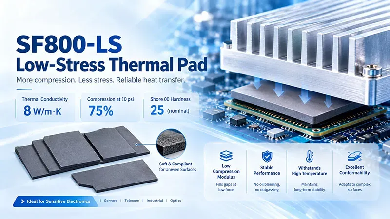
1. The Bind: Heat Wants a Hug, Your Board Can’t Take One
Strip the problem down and it’s a three-way tug-of-war. Thermal performance pushes you toward more clamping force — better contact, thinner heat path, lower interface resistance. Structural reality pushes back: board bow, BGA stress, cracked packages, housings that pop their snap-fits. And long-term reliability sits in the corner, silently asking whether the material will still behave itself after a few thousand hours at temperature. Turn any single knob and one of the other two complains.
This is why “low stress” needs to be a number, not an adjective. The compression modulus tells you how the reaction force builds as the pad is squeezed — and for large contact areas, remember that total force is pressure times area. A pad that feels gentle under your thumb can still add up to serious newtons across a 40 × 40 mm footprint. If your structure’s force budget is tight, the pad has to do its gap-filling at a fraction of the pressure a typical pad demands.
2. Compression Character: 75% at 10 psi, and Why the Ceiling Matters
SF800-LS’s calling card is its compression behavior. In Sheen’s internal comparison testing, compression under pressure looks like this:
| Pressure | Compression |
|---|---|
| 10 psi | ≈75% |
| 20 psi | ≈85% |
| 30 psi | ≈88% — approaching maximum compression |
Table 1. SF800-LS Thermal Pad: Compression Ratio Data Table (at 10–30 psi Pressure)
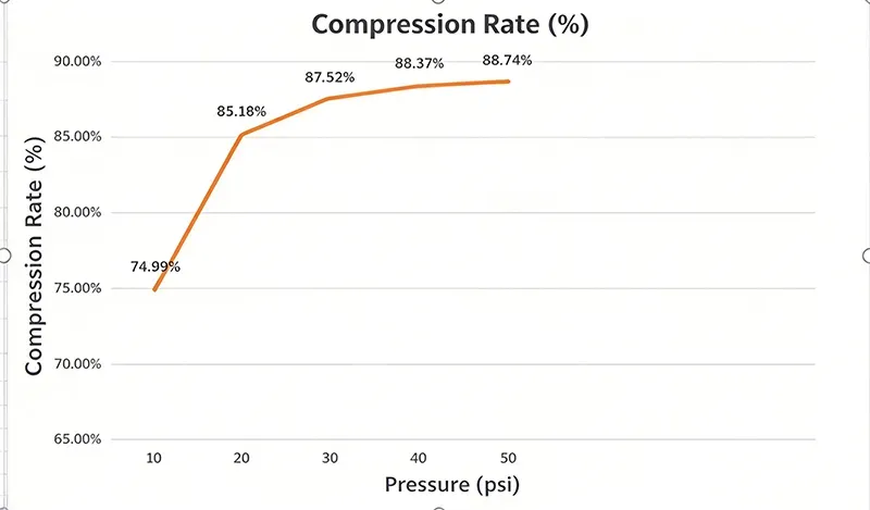
Figure1. SF800-LS Thermal Pad Compression Ratio Curve
Two readings matter here. First, the working range sits in the low-pressure band. A typical gap-filling pad wants 30–50 psi before it really starts conforming; SF800-LS has already given up three-quarters of its thickness by 10 psi. For force-limited structures, that means real gap-filling without asking the mechanics to punch above their weight. The TDS line “low compressive stress ≤150 N” — measured on a 2 mm specimen compressed 50% over a 28.6 mm diameter indenter — is the same story in lab language.
Second, 88% is the ceiling, not a target. Past maximum compression, thickness stops dropping and the material starts looking for somewhere else to go — lateral squeeze-out, edge overflow, long-term creep. Think of it like packing a suitcase: once everything’s in, sitting on it doesn’t create more room, it just strains the zipper. When sizing assemblies, aim for the 75–85% band and leave the last few percent alone.
One honest warning before anyone falls in love with the compression numbers: high compression does not automatically mean low thermal resistance. Compression thins the path and improves contact, sure, but the figure that counts is measured resistance per ASTM D5470. The catalog value for SF800-LS — 0.07 °C·in²/W at 50 psi, 2 mm — was measured at several times the pressure of this pad’s comfort zone. Don’t extrapolate 50 psi data down to a 10 psi assembly. Ask for the curve, and evaluate resistance at your actual clamp conditions.
3. The Spec Sheet, Read Properly
| Property | SF800-LS | Test Standard |
|---|---|---|
| Color | Gray | Visual |
| Thickness | 1.0–5.0 mm | ASTM D374 |
| Density | 3.45 ± 0.3 g/cm³ | ASTM D792 |
| Thermal conductivity | 8 W/m·K | ASTM D5470 |
| Hardness | Shore 00 25 (30 s) | ASTM D2240 |
| Thermal resistance @50 psi, 2 mm | 0.07 °C·in²/W | ASTM D5470 |
| Low compressive stress | ≤150 N (2 mm, 50% compression) | — |
| Breakdown voltage @1 mm, AC | ≥4 kV | ASTM D149 |
| Volume resistivity @250 V | ≥10¹³ Ω·cm | ASTM D257 |
| Dielectric constant @1 MHz | ≥6 | ASTM D150 |
| Operating temperature | −40–125 °C | — |
| Flammability | UL94 V-0 | — |
| Environmental compliance | RoHS / halogen-free / REACH pass | IEC 62321 / EN 14582 / EN 14372 |
Table 2. Source: SF800-LS TDS, version 20260807V1. The compressive stress figure uses a 2 mm specimen compressed 50% over a 28.6 mm diameter circular indenter.
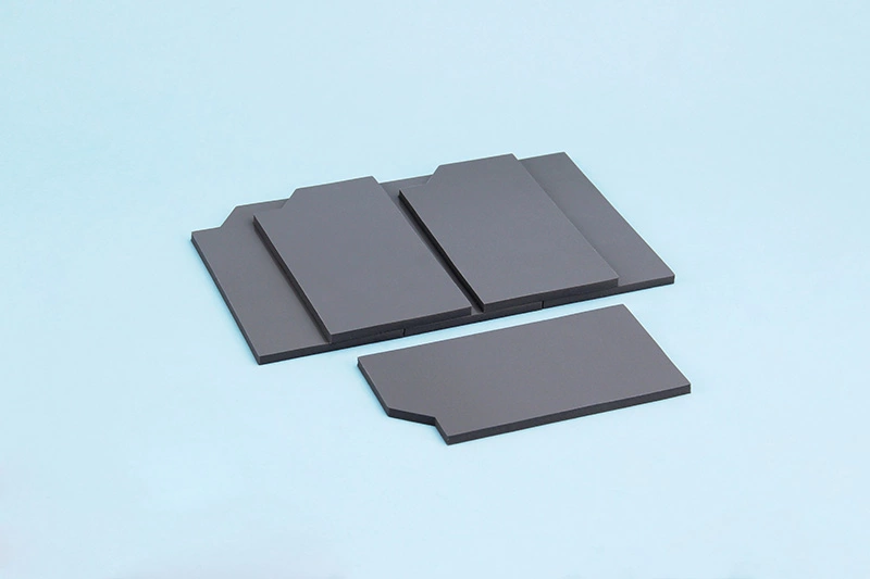
Figure2. Sheen Technology SF series Thermal pad products
Three reading notes before the table becomes gospel:
- The 8 W/m·K figure is for the base material without auxiliary layers, while density and hardness describe the finished part. When comparing vendors, confirm everyone is quoting the same basis — it’s an easy place to accidentally compare apples and oranges.
- ≥4 kV breakdown at 1 mm is a dielectric strength data point, not a working-voltage rating. Never promote a material breakdown voltage to the device’s long-term operating voltage — system insulation design needs its own margin.
The 1.0–5.0 mm thickness range marks this as a gap-filling material. If you’re dealing with a thin lid-to-cold-plate interface, that’s a different job — evaluate thermal grease or phase-change material there instead of forcing a pad into a role it wasn’t cast for.
4. Outgassing and Oil Bleed: The Slow-Motion Saboteur
Volatility problems are the slow-motion sabotage of thermal design. Siloxane volatiles drift, find a cold surface, and condense — onto optical lenses, sensor windows, gold-plated contacts. The failure rarely announces itself. It shows up late in system debug, disguised as a mysteriously foggy lens or a contact that went flaky, and by then the rework bill is painful. For any pad sitting near optics or sensors, volatiles aren’t a footnote. They’re a gate.
In side-by-side testing against a customer’s sample at 150 °C for 4 hours, SF800-LS’s volatile profile looked like this:
- Condensable volatiles: the customer sample showed clearly visible condensate. SF800-LS showed only a faint trace — for practical purposes, essentially none.
- Oil bleed: the customer sample produced a 9–10 mm oil ring. SF800-LS: 9–10 mm oil ring.
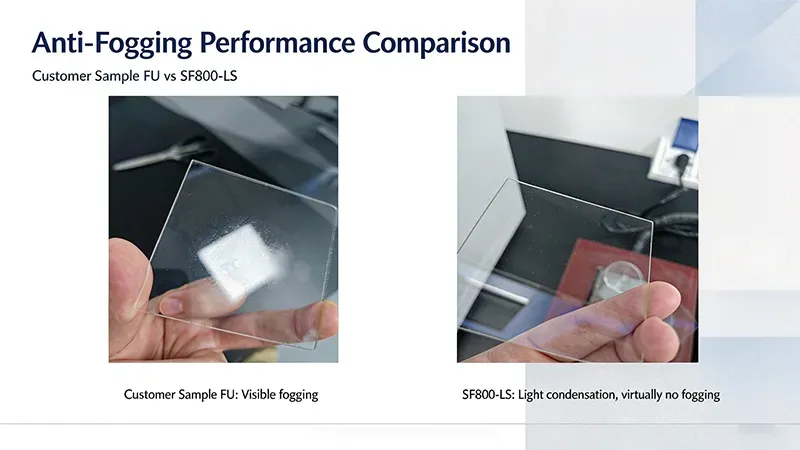
Figure3. Comparison of Volatility: SF800-LS vs. Customer-Provided Condensate Sample
If your design is contamination-sensitive, here’s a workflow suggestion: run the condensate and oil-bleed checks as admission tests, before anyone argues about a 1 W/m·K conductivity delta. A pad that wins on thermal paper but fogs your optics is not the cheaper pad.
5. 1,000 Hours at 125 °C: The Hardness Doubled. The Stress Didn’t Flinch.
Aging is where soft materials get cross-examined. Sure, it conforms beautifully today — but what about year three? Will it harden, crack, turn to chalk, and hand back every bit of assembly stress it once saved you? SF800-LS went through a 1,000-hour, 125 °C high-temperature aging test at Sheen’s reliability lab (2.0 mm specimen, tested June–July 2026), and the raw numbers are worth reading line by line:
| Aging Time | Hardness, Shore 00 | Avg. Compression Force, N |
|---|---|---|
| As received | 22 | 107.49 (109.85 / 107.25 / 105.36) |
| 200 h | 21 | 107.95 |
| 400 h | 21 | 90.24 |
| 600 h | 22 | 110.14 |
| 800 h | 38 | 128.99 |
| 1000 h | 43 | 111.81 |
Table 3. Aging in a constant-temperature oven at 125 °C. Compression force measured at 50% compression, 5 mm/min; hardness per Shore 00, 30 s dwell. Averages of three measurements.
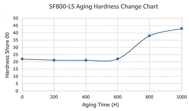
Figure4. SF800-LS aging Hardness Change Chart
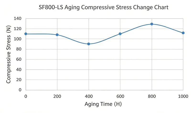
Figure5. SF800-LS aging compressive Stress Change Chart
Let’s read it honestly. The hardness climb is real: 22 to 43, nearly double, with the steep section arriving after 800 h. That’s textbook silicone thermal aging, and this article won’t pretend otherwise. But here’s the plot twist — the compression force barely moved. It stayed inside a 90–130 N band the whole run and finished at 111.81 N, statistically a shrug. Why does that matter? A durometer reads local indentation; your assembly feels full-area reaction force. The number that stresses your components is the one that held steady. In plain terms: the pad stiffens a bit with age, but it doesn’t turn into a brick leaning on your components.
Surface condition after 1,000 hours seals the story: no cracking, no powdering, and the pad kept its tack. The interface stays intact — no crumbly debris working its way into neighboring electronics. The lab’s verdict: aging feasibility preliminarily confirmed.
Fair warnings, because no single test covers a design life: doubled hardness does change surface-conforming behavior, so for extreme-gap designs it’s worth re-measuring thermal resistance on aged samples. And this is one condition — 125 °C, dry heat. If your product runs hotter, or swings through thermal cycles, ask for that validation too rather than assuming it.
6. Where SF800-LS Earns a Spot on Your Candidate List
Filter applications by one question: is the assembly’s force budget tight enough that a conventional pad is a non-starter? Where the answer is yes, SF800-LS deserves sampling consideration:
- Semiconductor test and fragile packages — test sockets and stress-sensitive devices where a low force ceiling is the entry ticket, not a preference.
- Communications and power equipment — dense board assemblies with limited fastener force and moderate heat flux; 8 W/m·K carries the load while 10 psi carries the assembly.
- Vehicle electronics and navigation — vibration plus long service life; compression-force stability after aging is exactly the bonus you want here.
- Memory and storage modules — multi-component height spreads are absorbed by material conformity, not by cranking clamp force.
These are evaluation directions, not grade assignments — every one of them still owes you a system-level validation.
7. Selection: Turn “Low Stress” into Numbers
Low stress is a specification waiting to happen. When requesting SF800-LS samples, arm your supplier with these inputs and the conversation gets productive fast:
- Gap limits, measured in the assembled state — component height spread, housing flatness, and PCB deformation all included. Loose-part measurements lie.
- Allowable pressure or total force — derived from the weakest component or structural member, not from how tight the screws feel.
- Target compression in the 75–85% band, with both limit cases checked: thinnest pad × largest gap (does it still touch?) and thickest pad × smallest gap (does it overload anything?).
- Temperature and service life — if operation approaches the 125 °C ceiling, ask for aging validation at your actual condition, not just the catalog one.
- Condensate and oil-bleed acceptance criteria — mandatory if optics, sensors, or plated contacts live nearby.
- Electrical requirements — withstand voltage and insulation resistance defined at system level, never borrowed from a 1 mm breakdown figure.
And when samples land, record the evidence in one pass: assembly imprint and compressed thickness, device temperature and heatsink temperature together, condensate and oil-bleed re-checks, and compression force before and after aging. That’s how “low stress” stops being a brochure phrase and becomes a row in your validation report.
【Request a Custom Quote】The best thermal pad was never the one with the biggest conductivity number. It’s the one that’s still pressed firmly in place ten years from now. SF800-LS’s 1,000-hour report suggests low stress and long-term reliability can share the same page — and that’s a page worth pinning to your selection checklist.
Sheen Thermal
Dongguan Sheen Electronic Technology Co., Ltd · Founded in 2008
Manufacturer of thermal interface materials and silicone foam for automotive electronics, energy storage, power electronics, communications and consumer electronics.
Certified
- ISO 9001:2015
- ISO 14001:2015
- IATF 16949:2016
What we supply
- Thermal conductivity Up to 90 W/m·K
- Thickness 0.3–10.0 mm
- Custom & samples Die-cut to drawing, 3–7 days
LAST:Nothing