
 English
 usheenthermal

When Chip Heights Vary, the Gap Filler Has to Adapt: Sheen SE Thermal Gels
Date:2026-11-11
Zoom into a circuit board. It's a tiny city.
Chips stand at different heights. Power devices scatter across the map like buildings on uneven ground. Metal shield cans and housings sit above them, playing the rooftops.
Now watch the heat try to leave town. Every joule has to cross the gap between its device and the “roof” first. And that stretch of road? Not flat. Not uniform. One chip touches the roof nicely. Its neighbor still has a pocket of air squatting in between. Press down hard enough to close the low gap, and the tall device eats the extra load.
Someone always loses.
This is the traffic problem Sheen's SE series thermal gels were hired to solve. The gel doesn't arrive as a pre-cut pad. It arrives soft, gets dispensed to the exact spot, then settles into whatever shape the local structure demands during assembly. Scattered heat sources, one heat path — that's the job description.
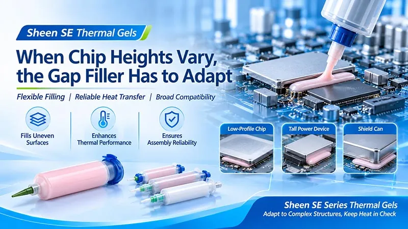
Figure 1. Sheen SE series thermal gels and their supply formats. Packaging and model selection are confirmed separately.
When the Gap Won't Cooperate, the Material Learns to Bend
Preformed pads are the tidy option. Easy to pick up, easy to place. They do well when the gap is known and the geometry is boring — in the best sense of the word.
But put one heatsink structure over several devices of different heights, and the juggling starts. Pad thickness here. Compression there. Placement everywhere. The design team juggles. The assembly team juggles. Nobody enjoys it.
The gel takes a different route to work. Here's the sequence:
- Dispense the right amount of gel to the right position — before assembly.
- Close the structure. The assembly gap itself decides the local shape of the bond line.
- Write the dispense pattern for each location into the equipment program. Repeatable, traceable, no cutting knife involved.
Think of the gel as a relay runner who's willing to bend. The handoff zone is ugly — tall here, thin there. The gel doesn't complain. It follows the terrain and passes the heat upward.
One honest caveat, though. Softness is there to improve contact and chase out trapped air. The allowable gap and the clamping load are still decided together with the device structure. The gel bends. It doesn't sign contracts.
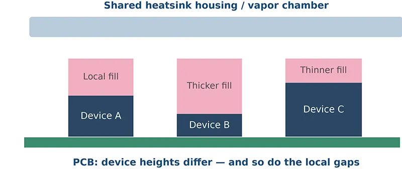
Figure 2. How the gel fills gaps of different heights under one shared housing. Pink indicates the thermal gel. Schematic only — not actual product scale; keep-out zones, creepage distances, and mechanical limits are not shown.
One-Part or Two-Part: Pick Your Assembly Rhythm
“Which one should I pick?” Start from how the line wants the material to behave — not from which brochure arrived first.
The one-part route is the straightforward one. The SE one-part gel described in Sheen's materials is a non-curing system, and its whole personality shows in three habits:
- No on-site A/B mixing. None. Open the package and dispense.
- It stays soft and plastic — always. It fills the local gap by simply being there.
- Best fit: assemblies that want fewer supply steps and a material that adapts on its own.
The two-part route ties filling to curing. A and B meet at the specified ratio. The reaction starts. The interface spreads during assembly. Then the material settles into a soft elastomer — a gel that remembers its shape.
That “formed shape” is genuinely attractive. But the process now has three stages to babysit:
- Mix ratio and mixing quality — sloppy mixing isn't a recipe tweak, it's a scrapped batch.
- Working time — the clock starts the moment A meets B.
- Cure state — confirm it, don't assume it.
| Comparison Item | SE One-Part Route | SE Two-Part Route |
|---|---|---|
| Preparation before use | No on-site A/B mixing required | Must be proportioned and mixed per model requirements |
| Forming path | Stays non-curing and plastic as described | Reacts after mixing and cures into a soft elastomer |
| Process focus | Supply stability, spreading, position retention | Mix ratio, mixing, working time, cure state |
| Natural starting point | Local gap filling with simplified dispensing | Local gap filling where curing is acceptable and post-cure shape matters |
Neither route is a structural fixing scheme. The gel's natural tack is a helper, not a fastener — the heatsink and housing still get fastened by whatever mechanical method the project specifies. Screws stay on the BOM.
From “It Fits” to “How Much Do I Actually Dispense?”
Volume cuts both ways. Under-dispense, and you leave contact-starved zones where the heat quietly gives up. Over-dispense, and after compression the gel goes sightseeing — into connectors, test points, keep-out areas.
So start with geometry. It's the cheapest math in the whole project. Take a 20 × 20 mm rectangular contact face:
Theoretical volume = coverage area × final gap.
Now run it at the 3.0 g/cm³ density listed in the SE30 data:
- 0.5 mm gap → 0.20 mL, about 0.60 g.
- 1.0 mm gap → 0.40 mL, about 1.20 g. Double the gap, double the bill.
- 1.5 mm gap → 0.60 mL, about 1.80 g.
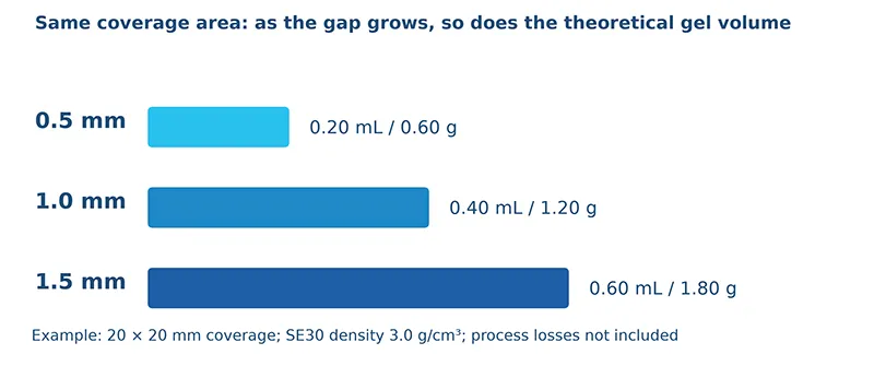
Figure 3. Geometric volume example — not a dispensing test and not a recommended volume. Real dispensing also has to account for spreading, voids, squeeze-out boundaries, residue, and structural tolerances.
Why bother with this arithmetic? Two reasons, really:
- It puts design and process on the same ruler — no more arguing past each other about “whether it's enough”.
- It sets a first budget, so the interesting arguments (below) start from a number instead of a vibe.
Because geometry is only the opening bid. The actual dispense volume still has to answer for:
- How the gel spreads from a bead or a dot.
- Whether it still covers the heat source after compression.
- Whether it stays clear of the keep-out zones.
- Squeeze-out, residue, and structural tolerances.
Design the volume together with the structure. That's how a flexible material becomes controlled assembly instead of a leap of faith.
SE30: The Résumé Behind the Soft Character
A gel is an assembly philosophy. A datasheet is where the philosophy signs its name. Take SE30 from the accompanying TDS: a flexible, silicone-resin-based thermal gap filler, equally happy being applied by hand or by dispensing equipment.
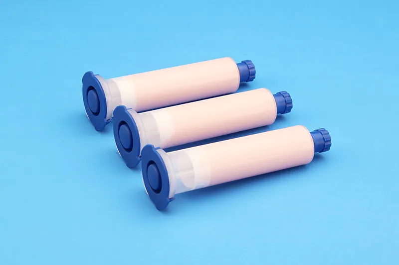
Figure 4. Sheen SE30 thermal gel Product Showcase
Three headline numbers set the frame:
- 3.0 W/m·K — thermal conductivity, the first-pass screening basis.
- 40 ± 5 g/min — extrusion rate, per the TDS conditions.
- 0.10 mm — minimum bond line thickness, a material parameter and nothing more.
| Item | SE30 | What It Means for Your Application |
|---|---|---|
| Thermal conductivity | 3.0 W/m·K | First-pass screening basis for thermal design |
| Density | 3.0 g/cm³ | Basis for volume-to-mass conversion of dispense volume |
| Minimum bond line thickness | 0.10 mm | A material parameter — not a recommended bond line for any given structure |
| Operating temperature | −50 to 150 °C | Model's usable range; not a whole-device lifetime promise |
| Volume resistivity | >10¹³ Ω·cm | Material electrical property information |
| Dielectric breakdown strength @AC | >4000 V/mm | Does not convert directly into device-level insulation withstand |
| Packaging / shelf life | 30 cc, 300 cc / 12 months | Subject to the purchased version and batch label |
Data source: the SE30 TDS page accompanying this article.
One number deserves special caution. The TDS also lists a thermal resistance of 0.055 °C·in²/W at 30 psi. Sounds great — but that row never says which bond line thickness it belongs to.
So this article refuses to turn it into a “your device runs N degrees cooler” promise. A number without its conditions is just a number wearing a costume. The material earns its results inside your actual interface, next to your actual structure — not as a headline standing alone.
Tight Spaces Are Where the Gel Earns Its Keep
Phones and Smart Speakers: A Path Under the Shield Can
Under a thermally functional metal shield can, processors, memory, and friends often sit at different heights. The gel gets dispensed zone by zone, builds the thermal connection into the can, and the can carries the heat onward.
In a space this small, three things deserve real engineering attention:
- Dispense location.
- Can stiffness.
- The spread boundary after compression.
“A bit extra, just to feel safe” isn't a strategy. It's how you buy a mess in millimeters.
77 GHz mmWave Radar: Cooling Close to the Source, Gel Away From Sensitive Zones
Sheen's retrieved application deck shows SE40 applied in the direction of mmWave radar. In a structure that compact, the gel can be designed around the gap between the target devices and the metalwork. But radar has a second personality — RF — and it gets a vote:
- RF and antenna regions need explicit keep-out boundaries. The gel doesn't get to volunteer itself into the antenna neighborhood.
- The material's dielectric properties and layout impact get checked, not assumed.
- Thermal design moves together with RF design — never ahead of it.
EOP Oil Pump Controllers: Handing the Heat to Metal in a Confined Housing
The same deck shows SE30 applied in the direction of EOP (electronic oil pump) controllers. Target hot zones on the control board pair up with the housing structure, and the gel plans the gap filling around them.
Two things get watched here, not one:
- Initial contact — did the gel reach everywhere it should?
- Staying power — after months in the working environment, is the gel still where you put it, and is the interface still healthy?
Model adoption still goes through project validation. The deck shows a direction; your project confirms it.
OBC and DC-DC: Different Interfaces, Different Jobs
Not every interface inside a power unit needs the same material. Some power devices need a thin, highly insulating interface scheme. Other board-level devices just need a local gap filled out to the housing. The gel takes the second job, working alongside thermal insulating sheets and pads — a team, not a solo act.
Two boundary lines, drawn clearly:
- Local gap filling is not potting the whole unit.
- A filled gap is not a finished electrical insulation system. That design still belongs to the project.
The applications above are organized from Sheen's application-direction materials. They are engineering scenario descriptions and do not imply that the listed models have been qualified by specific customers, automotive platforms, or complete devices.
【Request a Custom Quote】A good gap filler gives uneven devices a fair shot at the same heat path. From a sliver of a gap inside a phone to the irregular hot zones inside a car controller, the SE gel is the material that follows the structure. And when your design wants a formed, soft elastomer after assembly — the two-part route picks up the next chapter of the story.
Sheen Thermal
Dongguan Sheen Electronic Technology Co., Ltd · Founded in 2008
Manufacturer of thermal interface materials and silicone foam for automotive electronics, energy storage, power electronics, communications and consumer electronics.
Certified
- ISO 9001:2015
- ISO 14001:2015
- IATF 16949:2016
What we supply
- Thermal conductivity Up to 90 W/m·K
- Thickness 0.3–10.0 mm
- Custom & samples Die-cut to drawing, 3–7 days
LAST:Nothing