
 English
 usheenthermal

Don't Trap Heat in the Box: How to Match a Thermal Potting Compound to a Real Module
Date:2026-11-18
Let me show you where a power supply's reliability really lives. Crack open the enclosure. Inside, I see power devices running hot, components standing at uneven heights, and gaps my eyes can barely catch. When heat, moisture, and vibration all knock on the same door, a well-chosen, well-poured compound becomes the piece that connects component performance to years of stable operation.
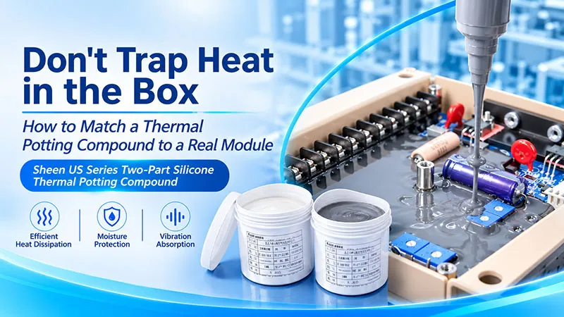
Figure 1. Sheen US-5201 Series Thermal Potting Compound Applications, the image does not represent one specific grade.
The material I am walking through today is Sheen's US series — a two-part silicone thermal potting compound. It arrives as a liquid, so it adapts to complex structures. After curing, it turns into a soft, elastic, thermally conductive and insulating layer, letting heat removal, moisture protection, and cushioning work together in the same space. From power modules to EV power electronics, from charging equipment to outdoor control units, my selection goal never changes: get the heat out smoothly, and let the devices work steadily.
If Heat Can't Leave, the Toughest Enclosure Becomes a Burden
Picture a compact DC-DC converter with me. The power devices generate heat nonstop, while transformers, inductors, capacitors, and connectors crowd around them at different heights, leaving gaps of every size. A flat thermal pad handles a proper contact surface nicely — but this three-dimensional, winding interior calls for a material that can flow into it.
Here is the paradox I always point out: a sealed structure helps environmental protection, yet it can also choke off internal convection. Without an effective path toward the housing or cooling structure, heat simply piles up in local pockets. Add condensation from outdoor temperature swings and vibration from a moving vehicle, and insulation and mechanical reliability both take the exam at the same time.
So what does potting compound really have to accomplish? Three jobs at once:
- Fill the space.
- Build a heat path.
- Keep protecting the components after curing.
That is why, when I select a compound, I never stop at conductivity. Flow behavior, insulation, hardness, and process fit all sit on the same checklist.
It Goes In as a Liquid — It Stays as a Thermal Shield
The US series is a two-part, silicone-based thermal potting material. The routine I follow: pre-stir components A and B separately, weigh them at a 1:1 mass ratio, mix thoroughly, degas, pour into the target zone — then cure at room temperature or with heat.
In its liquid stage, the compound adapts to the most awkward potting geometry I can throw at it. After curing, the soft elastic body wraps the components and builds heat paths wherever it makes effective contact with the housing. For a designer, that is like organizing scattered interior space into a usable cooling corridor.
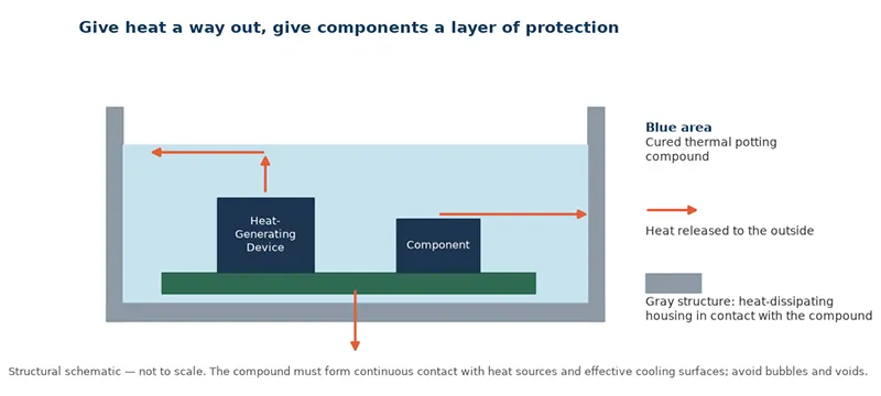
Figure 2. Thermal potting structure and heat path schematic.
Heat travels along a chain: heat-generating device → thermal potting compound → heat-dissipating housing or structure → the outside environment. Meanwhile, the coverage keeps moisture from reaching the circuitry directly and adds a cushion around components. But I want to be honest about the condition attached: the result depends on material, structure, and workmanship together. If the cooling surface is not properly connected, or a big bubble hides inside, the prettiest conductivity number in the world will not save you.
From 1 to 3.5 W/(m·K): Room on the Ladder for Every Heat Load
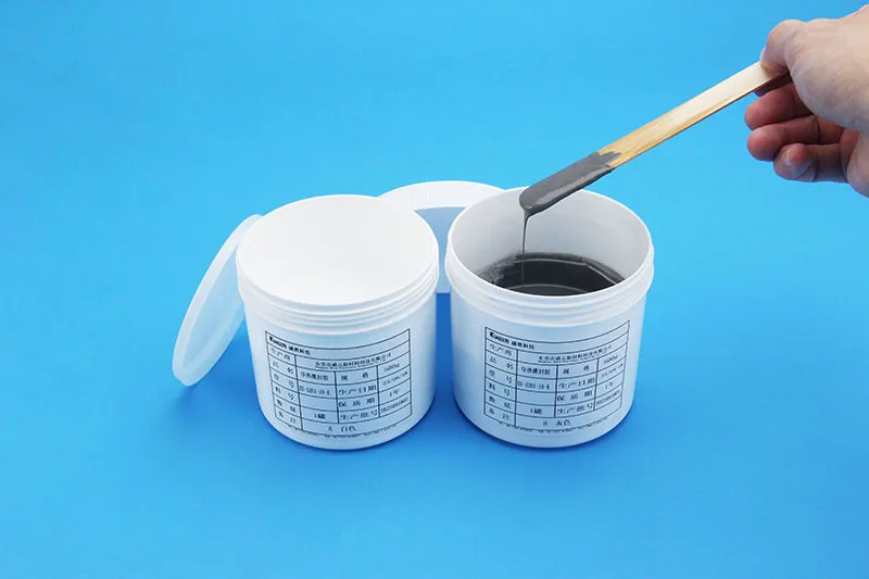
Figure 3. Sheen US-5201 Series Thermal Potting Compound Product Image, the image does not represent one specific grade.
Different heat loads and different potting structures naturally call for different models. Sheen's US series offers several conductivity rungs, so a project can converge step by step around target temperature rise, potting volume, and production conditions:
| Model | Conductivity W/(m·K) | Density g/cm³ | Selection Direction |
|---|---|---|---|
| US-5201-10 | 1.0 ± 0.1 | 1.8 ± 0.2 | General cooling needs with low potting weight gain |
| US-5201-15 | 1.5 ± 0.15 | 2.0 ± 0.2 | Balancing conductivity against compound weight |
| US-5201-20 | 2.0 ± 0.2 | 2.5 ± 0.2 | Evaluation for medium heat loads and compact power modules |
| US-5201-30 | 3.0 ± 0.3 | 2.9 ± 0.2 | Projects demanding more heat transfer through the layer |
| US-5201-35 | 3.5 | 3.1 ± 0.1 | Higher conductivity rung; process parameters to be confirmed separately |
*Selection directions are engineering suggestions based on material parameters — not verified customer applications.
For batch potting, density carries real weight — literally. Run the arithmetic with me: for a theoretical net potting volume of 100 cm³, US-5201-10 at its nominal density uses about 180 g of compound, while US-5201-30 uses about 290 g. There is no simple winner here. The first adds less weight; the second conducts better. The module's thermal design, weight budget, and cost target have to decide together.
Triple the Conductivity — Does Temperature Drop Threefold?
I hear this hope at almost every selection meeting. To see it clearly, I first separate “material conduction” from “system cooling.” For a simplified one-dimensional steady-state model, the layer's bulk resistance follows:
R = t ÷ (k × A)
where t is layer thickness, k is conductivity, and A is effective heat-transfer area. Thicker layer, bigger resistance. Higher conductivity and larger effective area, easier heat flow.
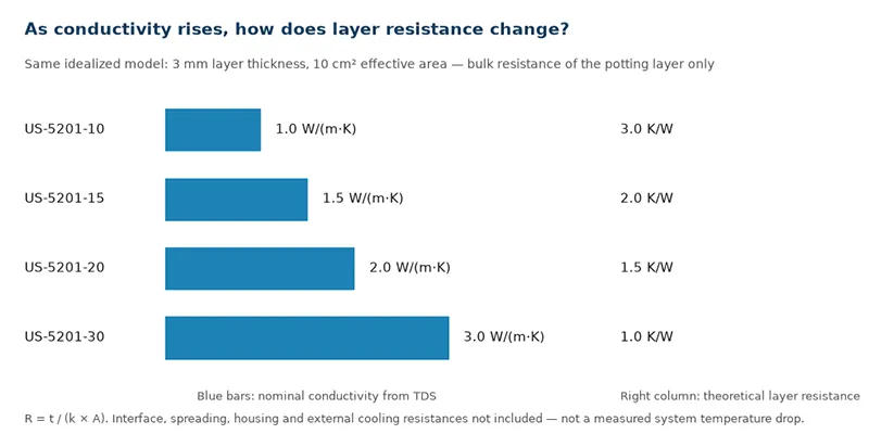
Figure 4. Conductivity vs ideal potting-layer bulk resistance.
Under the figure's identical thickness and area, raising conductivity from 1.0 to 3.0 W/(m·K) cuts the ideal layer resistance from 3.0 to 1.0 K/W — about 67% less. Improving conductivity genuinely improves that stretch of road. But it does not mean the whole system runs 67% cooler. Real temperature rise still answers to contact interfaces, component layout, heat spreading, the housing, and external cooling conditions.
So when I plan a material upgrade, I make it answer three questions at once:
- Can we remove wasted layer thickness?
- Can we enlarge effective contact with the cooling structure?
- Can we keep bubbles and voids under control?
Only when material parameters and structural design cooperate does paper conductivity turn into module-level cooling.
Heat Gets Out — Current Stays Contained
In power electronics, I never evaluate cooling and insulation separately. According to the four standalone TDS documents, US-5201-10, -15, -20, and -30 share these markings:
| Property | TDS Marking | What It Means for Selection |
|---|---|---|
| Material service temperature | −40 to 150 °C | Material-level reference range for temperature fit |
| Cured hardness | Shore 00 60–80 | Soft and elastic — helps cushioning and stress management |
| Volume resistivity | ≥10¹² Ω·cm @250 V | Reference for electrical insulation selection |
| AC breakdown voltage | ≥10 kV | Marked on a mixed 2 mm specimen — read it with its test conditions |
| Flame retardancy | UL 94 V-0 | Material flammability rating; verify the report and specimen conditions separately |
That soft elasticity suits potting designs that juggle heat removal and stress management. Components, PCB, and metal housing never expand and contract in perfect sync as temperature swings; a compliant encapsulating layer helps absorb those differences.
But I insist on using the parameters correctly, and I keep a short boundary list:
- Shore 00 is not Shore A.
- A specimen's breakdown voltage is not the device's allowable working voltage.
- A material temperature range never replaces device lifetime and temperature-rise validation.
Once those boundaries are clear, the datasheet can finally serve the design.
From Vehicles to the Outdoors: Let the Application Decide the Pour
EV Power Electronics — Compact Space, Cooling and Cushioning Together
On-board DC-DC converters, OBCs, and related power management units can face continuous heat, tight space, vibration, and thermal cycling all at once. The US series can be evaluated for electronic modules that need potting — wrapping irregular components, connecting to the cooling housing, and covering conduction, moisture protection, and cushioning in one step. For local high-heat-load zones, I would start with US-5201-20 or US-5201-30, then test against real heat distribution, layer thickness, and the potting process. Vehicle applications also need validation against actual substrates, thermal cycling, and vibration — and note this: potting an electronic module is not the same job as cell bonding or battery-pack potting.
Charging Equipment and High-Power Supplies — Reach Every Corner
In charging power supplies, industrial supplies, and related power modules, transformers, inductors, and power devices sit packed together. Thermal potting compound fills and wraps the zones suited to potting and assists heat transfer where it contacts the housing well. For these applications, I watch one question above all: “did the pour actually get there?” Whether the compound enters narrow slots, whether air lingers around coils, and whether thick sections cure fully all shape the final result. Model selection has to consider conductivity and the equipment's mixing, degassing, and dispensing conditions together.
Outdoor LED Drivers and Control Modules — Give Moisture and Temperature Swings Less to Work With
Outdoor devices fight load heat plus day-night temperature swings, humidity, and possible condensation. For LED drivers and outdoor control units designed around potting, the US series can be evaluated as a thermally conductive, insulating, moisture-protective material. The potting design must cooperate with the enclosure, cable exits, and sealing structure: continuous, complete coverage matters, and so does compatibility between compound, cables, and housing. The finished unit's protection rating should be confirmed by testing the complete structure.
Industrial Sensors and Control Units — A Flexible Blanket for Delicate Circuits
For sensor circuits, connector back ends, and small control modules suited to potting, thermal insulation and flexible encapsulation can enter the design together. When heat loads are mild, I would evaluate US-5201-10 or US-5201-15 first; for weight-sensitive structures, the density figure deserves a seat in the dosage calculation from day one. And one planning habit I never skip: mark the keep-out zones in advance — pressure-sensitive structures, optical windows, moving mechanisms, and areas that must stay open to sense the world. The compound should reach what needs protection and leave functional areas their room.
From a Bucket of Compound to a Stable Device: Process Is the Deciding Mile
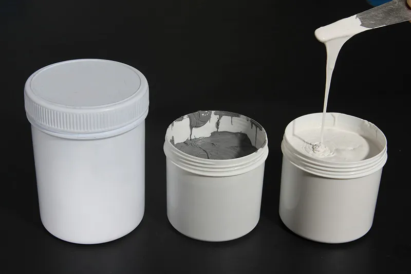
Figure 5. Sheen US-5201 Series Thermal Potting Compound Liquid form, the image does not represent one specific grade.
Material selected — now every batch has to land as close to the same result as possible. My US-series workflow in one line: pre-stir each component → weigh by mass → mix thoroughly → vacuum degas → pot → cure and inspect.
Stir first, weigh second. If filler has settled, stir components A and B separately until uniform, then weigh at the 1:1 mass ratio. A uniform color after mixing helps me read the mix state — but a pretty color never replaces metering accuracy.
Let the compound in, and let the air out. Degas per the product process requirements, and combine pour direction with the structure's venting design to cut down air carried in by mixing or trapped during potting. Devices and mixing containers stay clean and dry; cure compatibility with substrates, flux residue, and other contact materials gets verified before mass production.
Put the cure conditions into the production rhythm. The standalone TDS use instructions offer these references:
| Cure Temperature | 15 °C | 25 °C | 35 °C | 80 °C | 100 °C |
|---|---|---|---|---|---|
| Reference Time | 12 h | 5 h | 3 h | 20 min | 10 min |
*Quoted from the cure reference table in the TDS use instructions — not a fixed production-tempo promise. The same TDS performance table separately marks full cure at 25 °C as ≥2 h and at 100 °C as ≥10 min; the real process should be confirmed together with potting depth, device temperature, and the cure-judgment method. Tack-free time never equals workable time.
Heat curing can optimize production tempo — on one condition: the components, housing, and cables must tolerate that temperature, and the compound must actually reach the required cured state. In the end, appearance, cure state, temperature rise, and whatever insulation and environmental validation the project calls for are what land the material's performance on the real device.
For projects evaluating a domestic alternative, the US series offers a selection starting point across several conductivity rungs. Whether a substitution fits has to be answered on the same devices under the same duty: compare temperature rise, insulation, cure compatibility, production efficiency, and total cost calculated per potting volume.
If your power module is looking for a potting solution against heat, moisture, or vibration, I invite you to Contact Sheen for selection and sample evaluation.
Let the compound fill the complex space. Let heat meet an effective path. Let the devices get the protection they deserve. Sheen's US series thermal potting compounds — one more step toward reliable operation, starting from material selection.
Sheen Thermal
Dongguan Sheen Electronic Technology Co., Ltd · Founded in 2008
Manufacturer of thermal interface materials and silicone foam for automotive electronics, energy storage, power electronics, communications and consumer electronics.
Certified
- ISO 9001:2015
- ISO 14001:2015
- IATF 16949:2016
What we supply
- Thermal conductivity Up to 130 W/m·K
- Thickness 0.3–10.0 mm
- Custom & samples Die-cut to drawing, 3–7 days