
 English
 usheenthermal

The Heatsink Is Doing Its Job. Why Is the Chip Still Complaining About Heat?
Date:2026-11-16
Processors run faster. Power supplies shrink. Devices keep gaining features — and heat keeps quietly raising the stakes. To hold temperatures down, engineers enlarge fin area, tune airflow, upgrade the heatsink, sometimes redesign the entire cooling path.
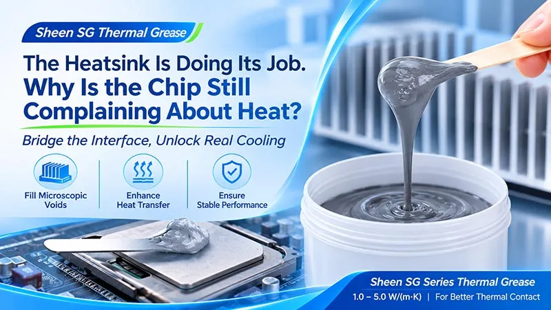
And yet, sometimes the heatsink is already excellent and the heat still camps around the device like an uninvited guest. The suspect hides in a spot that is easy to overlook: the contact interface between the hot device and the heatsink — a layer nearly invisible to the naked eye.
Put a chip lid against a heatsink base and you see two flat surfaces. Zoom in, and they look like two mountain ranges. Peaks touch peaks. Valleys hold air. And air, thermally speaking, is a squatter that refuses to move: it blocks the heat path and pays no rent.
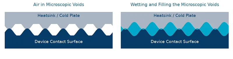
Figure 1. Interface filling schematic. Microscopic roughness is exaggerated for visibility — not to scale.
Think of a wide highway that squeezes into a narrow alley right at the entrance. The heatsink's job is to carry heat away; the grease's job is to get heat aboard in the first place. Sheen's SG thermal grease series wets the contact surfaces and fills the microscopic voids, helping heat cross the interface so the cooling hardware behind it can actually do its job. With a conductivity ladder from 1.0 to 5.0 W/(m·K), the series offers selection room for different thermal designs, assembly processes, and cost targets. This article walks through the series data, the SG560-40 TDS, and real application positions — how to turn material performance into measured cooling.
Thicker Is Not Safer: The Math of a Grease Layer
Grease does not work like a blanket. More is not warmer — here, more is slower. For a uniform material layer, bulk thermal resistance = thickness ÷ (conductivity × area). With material and area fixed, a thicker layer simply lengthens the road heat has to walk.
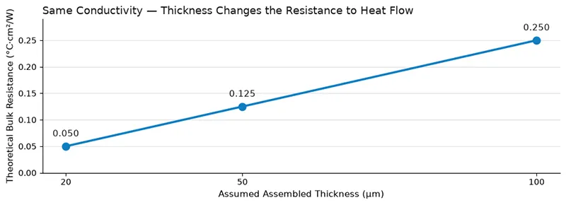
Figure 2. Theoretical calculation example at k = 4.0 W/(m·K). Contact resistances on both sides not included — not a measured product result.
From 20 μm to 100 μm, the theoretical bulk resistance multiplies by five. So the dispensing target is precise:
- Cover fully and fill the microscopic voids.
- Form a thin, uniform, continuous layer.
- Avoid both failure modes — too little means starvation voids, too much means a thick layer or squeeze-out.
Five Grades, One Starting Point
Different hardware asks different questions. A conventional power supply cares about cost and throughput. A compact control board cares about assembly space. A continuously running processor makes you count every slice of thermal resistance. The SG series offers five conductivity grades so you can screen around the real target:
| Model | Conductivity W/(m·K) | Thermal Resistance °C·in²/W | Min. Interface Thickness mm | Density g/cm³ |
|---|---|---|---|---|
| SG560-10 | 1.0 | 0.050 | 0.02 | 2.0 |
| SG560-20 | 2.0 | 0.034 | 0.02 | 2.2 |
| SG560-30 | 3.0 | 0.025 | 0.05 | 2.5 |
| SG560-40 | 4.0 | 0.015 | 0.02 | 2.6 |
| SG560-50 | 5.0 | 0.009 | 0.02 | 2.8 |
Thermal resistance values are listed at 30 psi. Data source: the accompanying series parameter table. Minimum interface thickness is not the thickness at which the listed resistance was measured.
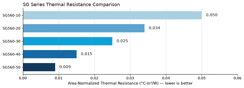
Figure 3. SG series area-normalized thermal resistance comparison. Source: accompanying series parameter table, at 30 psi.
By the listed numbers, SG560-40's resistance is about 70% lower than SG560-10's, and SG560-50's about 82% lower. Useful for a first screen — but please read the fine print: this does not mean the chip temperature drops 70% or 82%. System temperature also depends on power, area, heatsink, airflow, and environment. Full test conditions such as actual thickness per model need further confirmation; the final comparison belongs inside the same real structure.
Spotlight on SG560-40: Numbers With Their Conditions Attached
SG560-40 combines a silicone grease matrix with metal-oxide fillers — a gray paste that puts heat transfer, thin-interface capability, and application process on the same selection sheet:
| Parameter | Accompanying TDS Value | Engineering Meaning |
|---|---|---|
| Thermal conductivity | 4.0 W/(m·K) | The material's heat-transfer capability |
| Area-normalized thermal resistance | 0.015 °C·in²/W @30 psi | Interface performance under the stated test condition |
| Minimum interface thickness | 0.02 mm | Reference for thin-interface design |
| Operating temperature | −45 to 150 °C | Check against the real working window |
| Viscosity at 25 °C | 350 Pa·s | Reference for dispensing equipment and process tuning |
| Thermal weight loss | <0.2%, 125 °C / 48 h | Mass change under that specific condition |
| Density | 2.6 g/cm³ | Dosage and volume accounting |
The TDS cites ASTM D5470 for conductivity and resistance. 0.015 °C·in²/W converts to roughly 0.0968 °C·cm²/W — the two area units must never be mixed.
No Cure, Straight to Assembly
Thermal grease needs no curing, which suits interfaces held in contact by mechanical structure. The accompanying material lists SG560-40 for manual application and screen printing, and for automatic dispensing processes. Prototypes can be applied under controlled conditions; small batches can use stencils or printing fixtures; mass production should validate repeatable dispensing capability.
Dry-Out Resistance — and the Interface After the Miles
The material lists dry-out resistance as a feature, backed by <0.2% thermal weight loss at 125 °C over 48 hours. One honest boundary: that figure cannot be extrapolated into a whole-device service life. Coverage, separation, pump-out, and resistance drift under temperature cycling, vibration, and interface deformation still need evaluation against your actual duty cycle. Initial thermal performance decides the starting point; the aged interface decides whether the grease can travel the full distance with the device.
Where the SG Series Earns Its Place
SG greases suit positions worth evaluating where contact surfaces mate well, a thin interface is needed, and mechanical structure keeps the contact. Follow that logic, and applications land on specific spots.
Computing and Embedded: Hand the Heat Over on Time
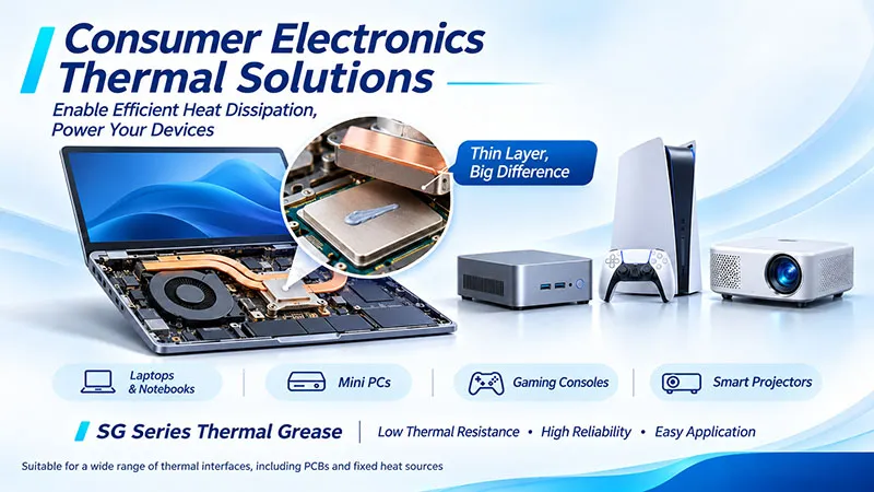
Figure 4. Consumer Electronics Thermal Management Scenarios Reference. Specific application scenarios require verification.
Laptops, desktops, industrial PCs, and edge-computing devices all face concentrated processor heat. Between the processor lid and the heatsink base, grease improves microscopic contact — the SG560-40 TDS lists high-frequency microprocessors, notebooks, and desktops as typical applications. During design, examine base flatness, retainer pressure, dispense volume, real thickness, and coverage after thermal cycling together. The processor works hard at computing; the interface has to keep pace.
Communication Equipment: Route Heat to the Heatsink or the Chassis
Processors, FPGAs, and other devices in communication equipment can build heat paths through heatsinks or metal housings. Small-gap, well-mated contact surfaces with stable fixing pressure are where the SG series can be evaluated. One device may need different materials in different positions — large gaps, multi-device height differences, or tolerance-compensation spots call for pads or gels instead. Choosing the right interface position beats spreading one material across the whole machine.
Power and LED: Unblock the Heat Exit in Compact Structures
Power adapters, industrial supplies, and some power modules move heat outward through metal bases, housings, or heatsinks. Where surfaces mate well and the structure allows a thin grease layer, the SG series is a candidate. One boundary worth bolding: the accompanying material provides no complete electrical-insulation data, so SG grease must not be treated as an insulating layer. Positions with withstand-voltage or insulation requirements need a separate insulating structure, verified independently.
In mechanically fixed, well-mated LED designs, grease can be evaluated between the metal-core board and the heatsink — the SG560-40 TDS lists LED lighting as a typical application. Confirm coverage and thermal performance against contact area, fastening method, and temperature after sustained operation. Light should keep flowing; heat should keep leaving.
Automotive and Precision Equipment: Validate From the Specific Interface
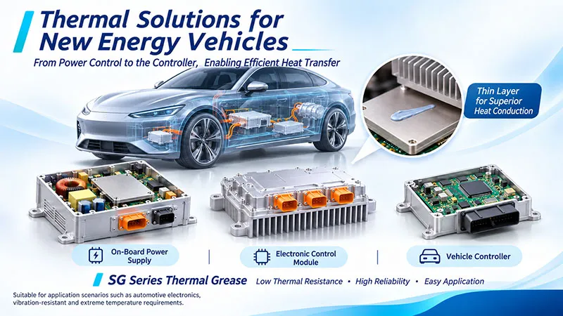
Figure 5. New Energy Vehicle Thermal Management Scenarios Reference. Specific application scenarios require verification.
Vehicle controllers, on-board power supplies, and some medical, security, and precision electronics may also hold positions suited to thin grease layers. Run sample evaluation around the defined structure, and add the extras the industry demands: vehicle vibration, temperature cycling, contamination sensitivity, or regulatory verification. An industry label is only a starting point — the contact surface's structure, environment, and duty cycle decide applicability.
From a Good Bead to a Stable Line
Getting grease onto one sample is easy. Getting every single unit dosed identically is the real gate into mass production. The dispensing guidance in the accompanying material can start your process trials — but the pressed, assembled interface is the only judge that counts:
| Step | Accompanying Guidance & Control Point | What to Verify |
|---|---|---|
| Cleaning | Clean device and heatsink surfaces | Choose a cleaner compatible with the substrates; dispense after drying |
| Initial coverage | Print area about 70–80% of the contact area | Complete coverage and squeeze-out after pressing |
| Stencil thickness | 0.08–0.12 mm recommended | Control the initial dose and verify repeatability |
| Assembly | Control pressure and fastening consistency | Real thickness, continuous coverage, local starvation |
| Aging | Design tests around real duty conditions | Coverage state and thermal performance drift |
Two thicknesses get confused all the time, and the confusion costs a trial run. The 0.08–0.12 mm stencil thickness describes the initial dispense; the 0.02 mm minimum interface thickness describes the assembled material layer. The final thickness depends on dose, flatness, pressure, and material flow. Likewise, printing 70–80% of the area at the start does not mean the final coverage stops there — verify spread after pressing, cover the target heat zone fully, and keep edge squeeze-out under control.

Figure 6. The dispensing validation flow, from surface cleaning to aging re-test.
The accompanying SG560-40 documentation lists a 12-month shelf life, stored ventilated, cool, and dry. Shelf life is not assembled service life; packaging, storage, and use conditions follow the latest confirmed documentation.
Count the Whole Ledger, Then Let the Interface Prove Itself
The cost of a thermal grease is never just the purchase price. The full ledger includes per-unit dosage, dispensing efficiency, assembly consistency, rework, and validation effort. With five conductivity grades, the SG series leaves room to match performance against cost. When evaluating a replacement for your current material, standardize the structure, power, ambient temperature, and assembly method — and record dosage and pressure. Compare initial performance first, then watch the aged temperature and interface state. That is how a datasheet advantage turns into project value:
| Comparison Item | What to Record |
|---|---|
| Initial thermal performance | Device temperature, ambient temperature, power, time to stabilize |
| Assembly and dosage | Per-unit dose mass, thickness, fastening method, coverage state |
| Production fit | Dispensing or printing consistency, cycle time, squeeze-out, cleaning requirements |
| Aged performance | Temperature change after defined duty, interface migration, coverage |
| Total cost | Material usage, process efficiency, rework and validation investment |
The accompanying material proposes import substitution and cost-optimization directions. The actual saving must be calculated from your project's quotation, dosage, and validation results — never treated as a fixed percentage for every project.
Inside every cooling system there is a big heatsink, carefully routed airflow, and one nearly invisible interface layer. Different jobs, one shared verdict: does the heat leave the device or not. If your heatsink has been upgraded and device temperatures still disappoint; if your current grease dosage refuses to behave and assembly results drift; or if the project needs to evaluate a new supply source — 【Request a Custom Quote】
One layer of grease connects two surfaces; one well-made selection connects thermal design to stable operation.
Sheen Thermal
Dongguan Sheen Electronic Technology Co., Ltd · Founded in 2008
Manufacturer of thermal interface materials and silicone foam for automotive electronics, energy storage, power electronics, communications and consumer electronics.
Certified
- ISO 9001:2015
- ISO 14001:2015
- IATF 16949:2016
What we supply
- Thermal conductivity Up to 130 W/m·K
- Thickness 0.3–10.0 mm
- Custom & samples Die-cut to drawing, 3–7 days