
 English
 usheenthermal

Thermal Management for 1.6T Optical Transceivers: Key Design Challenges
Date:2026-09-02
Thermal management for 1.6T optical transceivers is tightening as power density rises inside compact packages. Concentrated heat from DSPs, lasers, and drivers must be controlled to keep temperatures within specification and protect service life.
Effective qualification weighs interface resistance, thickness, compression, processability, reliability, and supply stability — not bulk conductivity alone.
Sheen Technology evaluates these factors across the thermal path to guide material and cooling selection.

Harmony Notes: Thermal Management for 1.6T Optical Transceivers
➔ Heat Flux Mapping: Trace thermal paths from DSPs, lasers, and drivers to prevent hotspots and ensure stable 1.6T operation.
➔ Cooling Selection: Match package density to heat rejection—microchannels or vapor chambers for compact builds; liquid cold plates for ultra-high rack densities.
➔ Interface Optimization: Use phase-change materials or gap fillers for uneven surfaces and graphite sheets or oxygen-free copper for rapid in-plane spreading.
➔ Design Validation: Employ infrared imaging and impedance testers to spot temperature gradients and verify low-resistance interfaces under real-world loads.
Request the 1.6T Transceiver Thermal Design Guide →
Thermal Management For 1.6T Optical Transceivers: Why It Matters
Thermal Management for 1.6T Optical Transceivers is getting tougher as power rises inside compact packages. Good cooling keeps temperatures in check, protects service life, and helps high-speed optics run steadily without nasty thermal surprises.
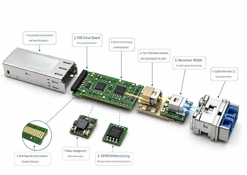
Understanding Heat Flux in 1.6T Modules
Thermal Management for 1.6T Optical Transceivers starts with knowing where heat builds up.
- Dense DSPs, lasers, and drivers raise power consumption and local thermal density.
- Mapping heat flux through substrates and housings reveals the temperature gradient.
Practical hotspot analysis then guides thermal dissipation, helping optical transceivers avoid unstable operating temperatures.
Reliability Risks from Inadequate Graphite Sheet Spreading
A graphite sheet works best when contact is broad and consistent.
Poor fit creates high thermal resistance. Weak thermal spreading raises junction temperature.
- A suitable thermal interface material, including gap filler for uneven surfaces, can reduce air gaps and support module reliability.
- Lower temperatures also slow heat-driven material degradation. That matters over years of service.
Note: a graphite sheet is electrically conductive and spreads heat in-plane. Use it on non-energized surfaces, or specify an edge-sealed / film-laminated variant near live conductors. Sheen Technology provide vertically oriented graphene thermal pad with edge-sealed that offers higher heat dissipation efficiency along the thickness direction, thereby reducing localized hotspots.
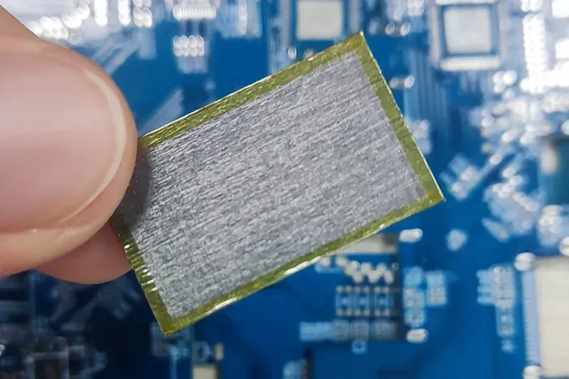
Performance Gains via Oxygen Free Copper Heat Paths
For Thermal Management for 1.6T Optical Transceivers, oxygen free copper provides a direct route for concentrated heat.
High thermal conductivity improves the heat path.
- Short copper routes toward a heat sink can boost cooling efficiency and overall thermal performance.
- Stable device temperatures may also support signal integrity. Sheen Technology can help match copper paths to tight module layouts.
Validating Thermal Designs with an Infrared Thermal Imager
Testing shows if 1.6T thermal management works outside the drawing board.
- An infrared thermal imager supports live thermal imaging. Engineers review temperature distribution and hotspot detection under load.
- Ongoing temperature monitoring supports thermal validation. Thermal impedance measurements add interface data, making design verification more grounded.
Which Cooling Methods Suit 1.6T Transceivers Best?
Thermal Management for 1.6T Optical Transceivers gets tricky as ports become denser and power rises. Good thermal management must move heat from optics and DSPs without eating up precious space. Thermal Management for 1.6T Optical Transceivers can use air, two-phase devices, or liquid cooling; the right call depends on heat load, airflow, and rack design.
Microchannel Heat Sink Advantages in Compact Packages
A microchannel heat sink packs large surface area into a compact package, giving 1.6T optical transceivers a practical way to improve heat dissipation.
Channel design matters:
- Good fluid dynamics improves heat transfer.
- Lower thermal resistance keeps component temperatures in check.
That makes Thermal Management for 1.6T Optical Transceivers easier when cooling space is tight.
Copper Vapor Chamber for Ultra-High Power Density
A copper vapor chamber handles high power density by using phase change to move heat quickly.
Heat reaches the chamber.
- Two-phase cooling transports thermal energy.
- High effective thermal conductivity supports fast heat spreading.
Heat reaches a wider cooling area.
- Better hotspot management helps protect DSPs and optical engines.
For Thermal Management for 1.6T Optical Transceivers, it is a neat fit for concentrated loads.
Pinned Copper Heat Fin: Passive Cooling Efficiency
Pinned copper heat fin designs boost passive cooling by exposing more copper to airflow. Smart fin geometry promotes convection from several directions, improving thermal efficiency and overall thermal performance without adding a pumped loop.
This approach works well when 1.6T transceiver heat remains manageable. Simple, but useful.
When to Choose a Liquid Cooling Cold Plate
At very high rack density, liquid cooling can outperform air cooling.
A cold plate supports:
- high heat flux removal near the device;
- steady temperature control.
The supporting coolant loop needs:
- a reliable pumped system;
- low-resistance contact for effective thermal management.
This cooling route suits installations where rising 1.6T optical transceiver loads push air systems beyond practical limits.
Cooling-method comparison for 1.6T transceivers:
| Method | Strength | Limitation | Best For |
| Microchannel sink | High area in compact space | Pump/plumbing, pressure loss | Compact high-flux builds |
| Copper vapor chamber | Wide spreading, low local R | Mfg complexity, orientation | Concentrated DSP/optic load |
| Pinned Cu fin (passive) | No pump, simple | Limited flux capacity | Manageable heat, good airflow |
| Liquid cold plate | Highest heat removal | Pumped loop, maintenance | Ultra-high rack density |
3 Key Thermal Interfaces In 1.6T Transceiver Packages
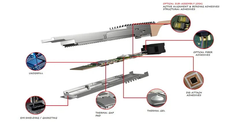
Thermal Management for 1.6T Optical Transceivers depends heavily on tiny contact zones where heat can stall. Sheen Technology focuses on matching interface materials to package gaps, pressure, and heat paths, helping 1.6T transceiver cooling stay practical and reliable.
Phase Change Material for Dynamic Gap Filling
Phase change material provides dynamic gap filling as temperature rises, softening enough to enter micropores that would otherwise trap air.
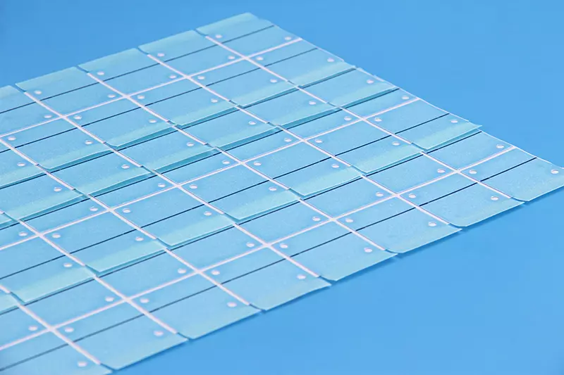
At the contact:
- Higher interface pressure improves conformity.
- Better contact cuts thermal resistance.
During operation:
- Improved heat dissipation helps protect the transceiver package.
- Thermal Management for 1.6T Optical Transceivers gains a repeatable interface without excessive squeeze force.
It’s a neat fit when small surface changes matter.
Thermal Grease: Low-Resistance Die Attach Solution
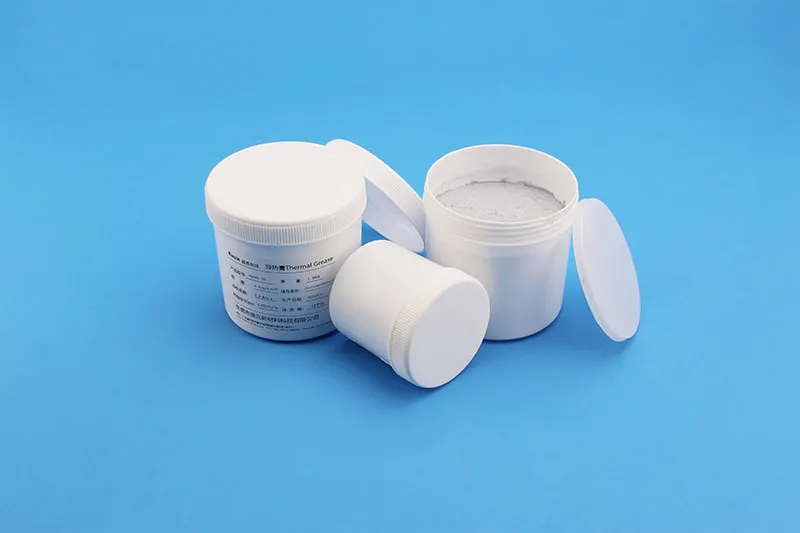
For tight interfaces, thermal grease creates a thin die attach path between an optoelectronic device and heat spreader. High thermal conductivity and a controlled bond line can deliver low thermal resistance, but there’s a catch: excess material can pump out during temperature cycling.
- Control dispense volume and thickness.
- Check spreading under assembly pressure.
- Validate high-temperature reliability over repeated cycles.
Sheen Technology evaluates these details because Thermal Management for 1.6T Optical Transceivers must remain stable beyond initial testing.
Thermal Gap Filler vs. Graphite Sheet Performance
For uneven interfaces:
Thermal gap filler
- Offers strong mechanical compliance.
- Follows changing surface roughness and package tolerance.
For lateral spreading:
Graphite sheet
- Provides high in-plane conductivity.
- Moves heat transfer sideways toward a larger cooling area.
Neither option wins every time. Required thermal performance depends on gap size, compression, and heat direction; Sheen Technology matches those factors to Thermal Management for 1.6T Optical Transceiver designs.
Interface-material comparison:
| Material | Strength | Limitation | Best For |
| Phase-change material | Dynamic gap fill, low BLT | Viscosity shift, migration | Variable gap, cycling |
| Thermal grease | Lowest resistance, thin BLT | Pump-out risk | Flat, tight interfaces |
| Gap filler | High compliance | Higher BLT | Uneven / tolerant gaps |
| Graphite sheet | In-plane spreading | Conductive; needs isolation | Lateral spread, non-live surfaces |
Thermal management for 1.6T optical transceivers is a design challenge across the full path. Sheen Technology provides interface materials, copper heat paths, and design-support for 1.6T transceiver thermal management.
→ Contact Sheen Technology for 1.6T Transceiver Thermal Design
Sheen Thermal
Dongguan Sheen Electronic Technology Co., Ltd · Founded in 2008
Manufacturer of thermal interface materials and silicone foam for automotive electronics, energy storage, power electronics, communications and consumer electronics.
Certified
- ISO 9001:2015
- ISO 14001:2015
- IATF 16949:2016
What we supply
- Thermal conductivity Up to 90 W/m·K
- Thickness 0.3–10.0 mm
- Custom & samples Die-cut to drawing, 3–7 days