
 English
 usheenthermal

Thermal Putty vs. Thermal Pad: How to Choose for AI Server Thermal Design?
Date:2026-09-24
Thermal Putty vs Thermal Pad isn’t a conductivity horse race. In AI servers, tiny gaps can become big thermal headaches, making contact, fit, and mechanical pressure just as critical as the number on a datasheet.
Putty tackles variable gaps; pads bring controlled thickness and repeatable placement.
The International Energy Agency reported in 2025 that data centers consumed about 415 TWh of electricity globally in 2024, underscoring the scale behind thermal-material decisions. For AI-server teams, that puts impedance, reliability, manufacturability, and volume qualification squarely on the table.
Reading Notes: Thermal Putty vs Thermal Pad
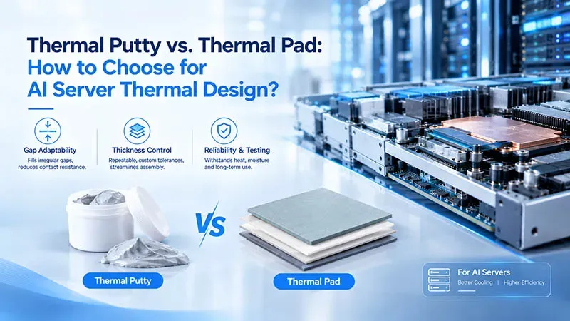
➔ Gap Adaptability: Thermal putty excels at filling irregular AI-server component gaps, reducing contact resistance where fixed-thickness pads struggle.
➔ Thickness Control: Die-cut pads offer repeatable, custom tolerances for uniform bond lines, streamlining high-volume assembly and minimizing process variation.
➔ Reliability & Testing: Evaluate pump-out, oil-bleed, high-temperature aging, and humidity exposure to choose the right interface for long-term AI-server performance.
Types Of Thermal Interface Materials Explained
Selecting an interface begins with four questions about the joint itself: the shape and flatness of the two surfaces, whether electrical isolation is required, how much mounting pressure the assembly can apply, and how much space the gap occupies. Thermal putty and thermal pad answer those questions differently, and AI servers, GPUs, power electronics, and storage each load the answers differently. Sheen Technology supports material selection around those practical constraints.
The four material families below are the ones that appear in AI-server thermal stacks. They are not interchangeable:
| Material family | Role in the stack | Governing property and typical range | Where it belongs |
| Silicone thermal putty | Gap-filling interface | Effective joint conductivity, typically 1–6 W/m·K measured on the bond line; Shore OO hardness typically 30–70; installed thickness set by assembly pressure | Variable or irregular gaps above processors and around adjacent components in AI servers |
| Silicone Thermal pad | Gap-filling interface | Effective joint conductivity, typically 1–15 W/m·K on the bond line; thickness held to a specified tolerance; compression range typically 10–30% | Predictable gap heights, high-volume placement, uniform bond lines |
| Phase-change material | Gap-filling interface (thin film) or transient buffer (storage class) | Transition temperature typically 45–65 °C; bond-line resistance falls once the material has softened and wet the surfaces | GPU and accelerator joints with high power density and a stable mechanical gap |
| Ceramic-filled Boron Nitride Thermal pad | Gap-filling interface with isolation | Dielectric strength tested per ASTM D149 or IEC 60243; effective joint conductivity typically 16 W/m·K | High-voltage power conversion modules where heat and current must be separated |
Table 1. Interface material families by role. Conductivity values are typical illustrative ranges for the categories and are datasheet-dependent.
Overview of Silicone Thermal Putty in AI Servers
For an AI server, silicone putty provides flexible gap filling around processors and nearby components.
- High deformation accommodates uneven heights.
- Controlled viscosity helps material stay where applied.
- Useful thermal conductivity supports heat dissipation with low contact resistance.

In Thermal Putty vs Thermal Pad, putty can make processor cooling easier when gaps vary a lot. Fixed pads remain handy for predictable spacing.
What Makes Phase Change Material Ideal for GPUs?
A phase change material starts firm, then softens near its designed melting point.
During GPU cooling:
- Heat raises the interface temperature.
- The material softens and improves surface contact.
Under sustained loads:
- Lower thermal resistance supports efficient heat transfer.
- Controlled latent heat behavior helps the interface material perform consistently.
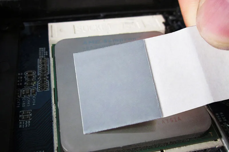
So, Thermal Putty vs Thermal Pad is not the whole story for GPUs; phase-change options bring another practical choice.
Ceramic Filled Elastomer for High-Voltage Power Conversion Modules
A ceramic filled elastomer suits high-voltage hardware where heat and current need careful separation.
For power conversion:
- Electrical insulation reduces conduction risk.
- Compression helps bridge normal tolerance differences.
For module cooling:
- Thermal stability supports repeated operating cycles.
- Sheen Technology can match dielectric and thermal needs to assembly conditions.
Here, Thermal Putty vs Thermal Pad comparisons should include voltage isolation, not just conductivity.
Graphene Thermal Sheet Solutions for SSD Cooling
Graphene thermal sheets offer unique advantages for SSD thermal management: their exceptionally high through-plane thermal conductivity facilitates rapid heat transfer across the thickness of the material. Their ultra-thin profile makes them suitable for compact assembly spaces, helping to conduct heat from the SSD to the chassis or a heat sink.
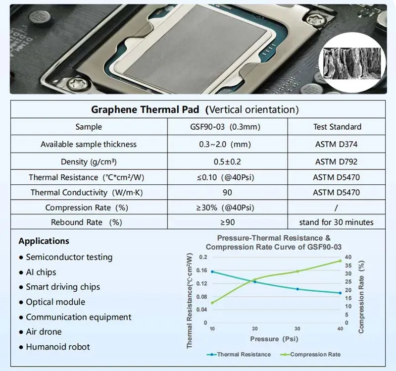
For slim hardware, Thermal Putty vs Thermal Pad remains useful, while graphite adds a thin heat-spreading route when vertical space is, well, pretty tight.
4 Key Parameters Of Thermal Putty Vs Thermal Pad
Thermal Putty vs Thermal Pad selection goes beyond a conductivity number. In AI servers, gap size, mounting pressure, production speed, and interface behavior all matter. Sheen Technology helps engineers compare thermal interface materials in practical designs, from prototypes through large production runs.
Thermal Conductivity: Heat Dissipation Rate Comparisons
Thermal Putty vs Thermal Pad ratings in W/m-K need context.
Conductivity
- Higher filler loading can raise heat flux through a silicone matrix.
- Actual dissipation rate also depends on contact quality.
System impact
- Lower thermal resistance helps control junction temperature, which is the real goal.
| Property | Thermal putty | Thermal pad (die-cut) | How it is established |
| Effective joint conductivity | Typically 1–6 W/m·K at the installed bond line | Typically 1–15 W/m·K at the installed bond line | ASTM D5470, at a stated bond-line thickness |
| Installed thickness | Set by assembly pressure and gap | Set by the die-cut part to a specified tolerance | Measured on a cross-sectioned assembly |
| Hardness | Shore OO typically 30–70; deforms readily | Shore OO typically 40–60 depending on grade | ASTM D2240, Shore OO scale |
| Compression range | Effectively continuous; limited by pump-out risk | Typically 10–30% of nominal thickness | ASTM D395 for compression set |
| Pump-out and bleed risk | Present; sensitive to thermal cycling and gap stability | Low; no flow path once compressed | ASTM E595 for outgassing; cycling per IEC 60068-2-14 |
| Assembly route | Dispensed; dosing repeatability governs the bond line | Placed; one part number per thickness step | Process capability study on the dispenser or placer |
| Dielectric strength | Formulation-dependent; tested in the supplied form | Formulation-dependent; tested in the supplied form | ASTM D149 or IEC 60243 |
Table 2. Thermal putty and thermal pad compared on the properties that decide a qualification. All numeric ranges are typical illustrative values for these product categories and are datasheet-dependent.
Hardness Durometer and Its Impact on Contact Resistance
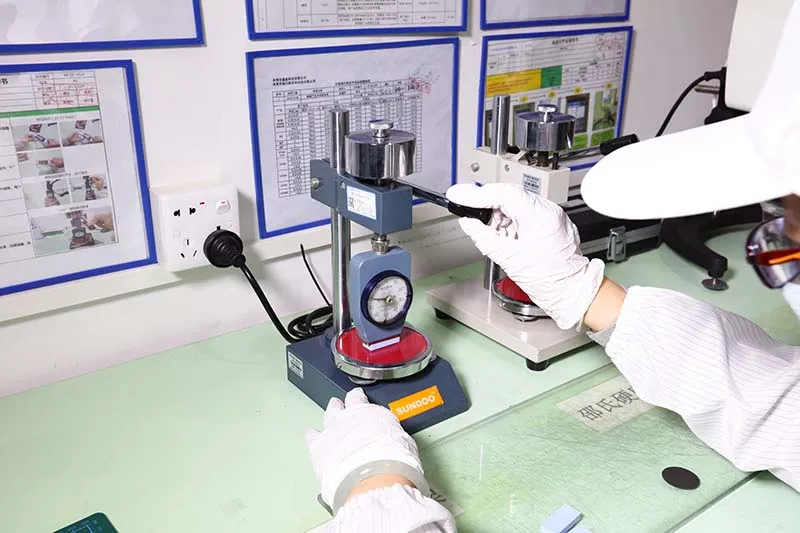
A softer thermal putty can settle around uneven hardware with less fuss.
- Check Shore OO hardness and expected compression force.
- Match deformation to the job.
- Good surface conformity supports gap filling.
- Lower interfacial resistance can follow.
- Limit mechanical stress on delicate components.
Thermal Impedance: Balancing Performance and Form Factor
Thermal Putty vs Thermal Pad performance changes with installed geometry.
- Fit:gap height and thickness tolerance determine practical bondline thickness.
- Contact:surface roughness and clamping pressure influence interface quality.
- Cooling:Better contact supports heat transfer and overall thermal performance.
Sheen Technology can support material choices when pad and putty options must fit tight AI server layouts.
Viscosity Index Effects on Automated Dispensing Systems
Putty brings production variables that pads largely avoid. Rheological properties change with shear rate, affecting flow rate and dispensing speed.
- Tune fluidity for stable dosing.
- Validate material behavior during robotic assembly.
- Check resistance to pumping out after repeated thermal cycling.
Is Thermal Putty Or Thermal Pad Right For You
Thermal Putty vs Thermal Pad choices come down to more than conductivity on a data sheet. Gap size, pressure, heat cycles, and aging all matter in the real world. A good call matches the thermal interface to actual operating conditions.
Have You Encountered Pump Out Degradation in Telecom Base Stations?
For telecom base stations, repeated heating and cooling can trigger the pump-out effect, pushing soft material away from the contact area.
Compare Thermal Putty vs Thermal Pad through reliability testing:
Under repeated thermal cycle exposure:
- Check oil bleed and movement.
- Measure changes in interface resistance.
After thermal shock:
- Inspect gap filling coverage.
- Look for cracking or separation.
A suitable thermal interface material should stay put when temperatures swing. That’s the key.
Need Custom Thickness Tolerance for Automotive ECUs?
In automotive ECUs, fit can make or break thermal contact. Thermal Putty vs Thermal Pad gives engineers two practical routes.
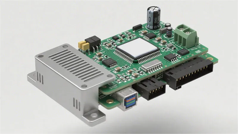
Pads offer controlled thickness tolerance and strong dimensional stability, making die-cut parts handy for a consistent electronic control unit gap. The required compression rate still matters because excess force creates mechanical stress.
Putty takes another path: it flows around uneven parts and changing gaps. For tricky layouts, this flexibility can reduce the need for custom molding.
Seeking Long Term Stability under High Temperature Aging?
Both materials should be judged after months at temperature, not on day one. Start with high-temperature aging and humidity exposure, at the maximum operating temperature the specification allows rather than at a nominal figure.
Track thermal degradation:
- Recheck thermal conductivity.
- Inspect silicone oil bleed.
Extend evaluation through accelerated life testing:
- Watch for cracking or hardening.
- Compare material aging trends.
Stability is a property of the pair, not of the category: a putty and a pad can both hold their contact for the life of the assembly provided the gap is mechanically stable and the operating temperature stays inside the material’s validated range. Testing under realistic aging conditions, with the drift figures recorded against the as-built baseline, is what establishes that for a specific design.
The selection rule that follows from the three subsections above is short.
- Choose a pad when the gap height is known, repeatable, and inside the material’s compression range, and when placement without a dispense step is worth the tooling cost.
- Choose a putty when component heights vary across the board or change between builds, when the gap is larger than a pad can serve at reasonable compression, and when the team can validate a dispense process and test for pump-out.
- Choose neither, and move to a phase-change interface, when the gap is stable and very thin and the power density is high.
| Decision point | Points to thermal pad | Points to thermal putty |
| Gap uniformity | Gap height known and held within the material’s compression range | Component heights vary across the board or from build to build |
| Gap size | Small to moderate gaps, typically under about 2 mm | Larger or irregular gaps where a pad would need excessive compression |
| Assembly volume and process | Placement is preferred; a dispense step is not available | A validated dispensing process is available and dosing can be controlled |
| Service life and rework | Low pump-out exposure is valued; rework means replacing a part | Gap tolerance is prioritised; rework means re-dispensing |
Table 3. Decision guide assembled from the criteria discussed in this section. The thresholds given are typical and illustrative; the compression range and gap ceiling of a specific material must come from its datasheet.
【Request a Custom Quote】Weighing putty against die-cut pads for uneven component heights, tight layouts, or high-volume lines? Send us your gap map and worst-case tolerance, available clamp pressure, target bond-line thickness, dispensing capability, and reliability requirements such as pump-out and high-temperature aging, and our engineers can recommend the thermal interface format that fits your AI server thermal design.
Sheen Thermal
Dongguan Sheen Electronic Technology Co., Ltd · Founded in 2008
Manufacturer of thermal interface materials and silicone foam for automotive electronics, energy storage, power electronics, communications and consumer electronics.
Certified
- ISO 9001:2015
- ISO 14001:2015
- IATF 16949:2016
What we supply
- Thermal conductivity Up to 90 W/m·K
- Thickness 0.3–10.0 mm
- Custom & samples Die-cut to drawing, 3–7 days
LAST:Nothing