
 English
 usheenthermal

Why Advanced Thermal Management for AI Server Design Is Critical
Date:2026-09-03
AI server thermal management is no longer a component-level problem. Accelerator package power has moved into the several-hundred-watt to kilowatt class per module, and rack power density in liquid-cooled AI deployments routinely exceeds air-cooled levels by an order of magnitude. In that regime, the largest single thermal resistance in the chip-to-coolant path is frequently not the heatsink or the cold plate — it is the interface layer between them.
This article examines why advanced thermal management is critical for AI server design from the thermal interface material (TIM) standpoint: where conventional approaches lose margin, how heat is distributed across an AI server assembly, which interface materials address which zone, and how to qualify them. Loop hardware — cold plates, pumps, couplings, sensors — is treated where it constrains the interface, not as a product category.
Key Points: Thermal Management for AI Server
→ Interface Optimization: Use phase-change materials, synthetic graphite sheets, or copper baseplates with direct liquid cooling cold plates to bridge gaps and spread heat efficiently.
→ Active Cooling Integration: Prioritize aluminum microchannel sinks, two-phase immersion modules, or vapor chambers paired with engineered thermal fluids and packless centrifugal pumps for consistent heat removal.
→ Predictive Monitoring & Maintenance: Deploy fiber-optic sensors, digital pressure transducers, leak-detection cables, and mass flow meters. Automate flow-control valves and quick-disconnect couplings for real-time alerts and rapid service to avoid hotspots, pressure drops, or unplanned downtime.
Request the AI Server TIM Selection Guide →

Why Conventional Cooling Loses Margin in AI Racks
Modern accelerators pack serious heat into tight spaces. Passive parts still help, but AI server cooling needs a clear path from chip to coolant. Sheen Technology supports this thermal management approach with cooling hardware designed for demanding computing systems.
The chip-to-coolant path in an AI server is a series resistance chain: die → lid → TIM1 → lid/spreader → TIM2 → cold plate → coolant. Every additional interface adds resistance, and the two TIM layers sit where the heat flux is highest. Air cooling has largely reached its practical ceiling for this class of hardware; the question is not whether to move heat into liquid, but how much resistance the interfaces on that path are allowed to contribute.
Why Passive Heat Sinks Fail in High-Density Racks
Passive sinks face rising thermal resistance as power density climbs.
Inside high-density racks:
- Dense server nodes restrict air movement.
- Higher airflow impedance weakens heat dissipation. Chip temperatures rise.
- Thermal throttling can cut sustained performance.
For thermal management for AI server platforms, aluminum microchannel heat sinks and direct-liquid cold plates give heat somewhere useful to go. Pretty simple: airflow alone can hit a wall.
The Limits of Thermal Conductive Silicone Grease
Silicone grease works as a thermal interface material, filling micro-voids and lowering interface resistance between mating surfaces. Its thermal conductivity, however, only moves heat across that thin joint; it does not reject heat from the server.
Repeated thermal cycling may also encourage the pump-out effect and polymer degradation. Sheen Technology pairs suitable interface materials with copper baseplates or active cooling, creating a more dependable AI server thermal solution.
Vapor Chamber Alone: Insufficient for AI Workloads
A vapor chamber uses phase change to spread severe hotspots, but spreading heat is only part of thermal management for AI server equipment.
Under high heat flux:
- The evaporator wick moves working fluid.
- Rising thermal load can approach condenser limits
At that point, direct liquid cooling or two-phase immersion modules provide the continuous heat rejection AI workloads need.
Hotspots Exposed: Mapping AI Server Temperature Zones
Good thermal management starts with knowing where heat builds and how cooling behaves around critical parts. Sensor data turns those hot spots into useful signals rather than guesswork.
Interface selection differs by zone, because each zone has a different combination of heat flux, gap tolerance, electrical exposure and service requirement. Treating the whole assembly with a single material is the most common source of avoidable thermal margin loss.
| Zone | Dominant Constraint | Interface Priority | Typical Material Route |
| CPU / GPU die-lid | Peak heat flux; lowest allowable resistance | Minimum BLT, full wetting | PCM or grease at TIM2; vertically aligned pad where rework is needed |
| Memory (DIMM / HBM stack) | Low height, tight spacing, moderate flux | Conformability at low pressure | Soft gap pad, low hardness, die-cut to profile |
| VRM / power stage | Cyclic load, moderate flux, tall components | Tolerance absorption | Gap filler or compressible gap pad |
| Network ASIC / NIC | Sustained load, defined lid height | Stable long-term resistance | PCM or high-conductivity pad |
| Lid-to-chassis spreading path | Directional mismatch: lateral vs. through-plane | Match material to flow direction | Synthetic graphite sheet (lateral) or PI film (isolation) |
*Zone names describe the interface location, not a specific OEM platform. Material routes are typical engineering practice; final selection is governed by the assembly drawing and datasheet limits.
CPU/GPU Die: Fiber Optic Temperature Sensor Insights
Chip-level readings
- A fiber optic sensor uses optical sensing without electrical interference.
- Fast die temperature changes expose peaks early.
Cooling response
- thermal monitoring supports quick hotspot detection, helping heat dissipation controls react before throttling kicks in.
Memory Modules: Thermocouple Probe Readings
Memory needs its own close watch because trapped heat can quietly reduce stability.
A thermocouple probe records memory temperature beside active DIMMs.
- Comparing positions maps the thermal gradient and DIMM thermal profile.
- Continuous temperature logging spots heat accumulation caused by weak airflow, giving server thermal management teams a practical heads-up.
Power Delivery Units: Digital Pressure Transducer Data
Coolant health
- A pressure transducer measures coolant pressure.
- Rising pressure drop may point to restrictions.
Cooling performance
- hydraulic monitoring connects pressure with flow rate.
- Those readings make fluid dynamics easier to diagnose when AI server cooling performance slips.
VRM Areas: Coolant Leak Detection Cable Alerts
Around each voltage regulator, leak detection needs to be quick.
A sensor cable provides a moisture alert near fittings.
- Early warning improves coolant safety.
- Controls can trigger thermal shutdown when fluid threatens powered hardware.
Talk to an Application Engineer About Your Thermal Zone Map →
Thermal Management for AI Server: Materials That Matter
Effective thermal management for AI server hardware starts with materials matched to each heat path, not just bigger cooling gear. From chips to circuit insulation, small material choices can make or break AI server reliability. Sheen Technology supports thermal management designs where heat control, electrical safety, and practical assembly all need to work together under heavy computing loads.
Phase Change Material for Ultra-Thin Interface Layers
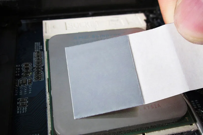
At the processor interface:
- A thermal interface material softens with heat, improving micro-gap filling between silicon and cold plates.
- A polymer matrix balances handling with useful conductivity.
In thermal management for AI server designs, thin bond lines cut resistance. Latent heat behavior also supports steady heat dissipation near demanding chips.
Vertically Aligned Graphene Thermal Pad
Where heat must cross the bond line rather than spread along it, a vertically aligned graphene thermal pad is the appropriate carbon-based choice. In this construction the graphene planes are oriented perpendicular to the pad faces, so the strong axis of thermal transport is the through-plane direction — the direction the heat actually travels between die and cold plate. This is the opposite of a graphite sheet, and the two are frequently confused in sourcing.
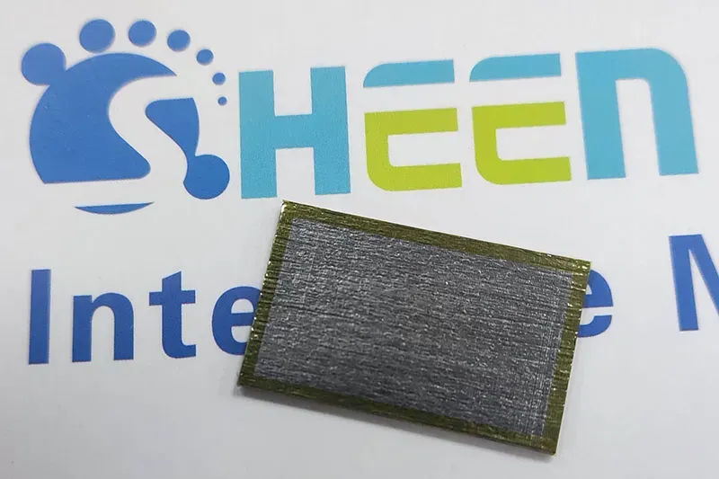
Because the aligned graphene network is continuous through the thickness, these pads reach high through-plane conductivity at moderate filler loading, which keeps them softer and more compliant than an equivalently loaded random-orientation pad. That combination — through-plane conductivity plus compressibility — suits interfaces with meaningful coplanarity error, such as accelerator modules on a shared cold plate.
Graphene is electrically conductive. Specify edge sealing or an insulating film lamination wherever the pad is adjacent to live conductors, and confirm the isolation scheme during qualification rather than after it.
Boron Nitride Thermal Pad — The Insulating Option
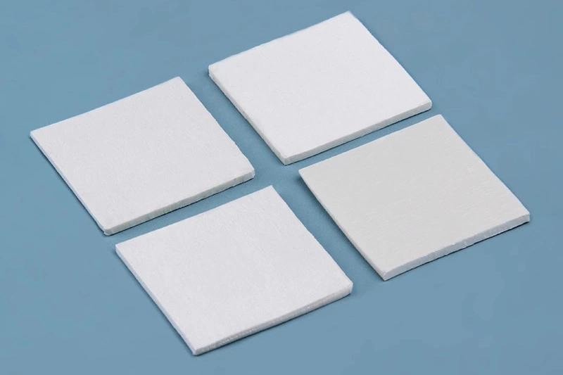
Where the interface must carry heat but block current, boron nitride (BN) filled pads are the reference choice. Hexagonal boron nitride combines useful thermal conductivity with high dielectric strength and low dielectric constant, so it can be used directly over exposed circuitry, power-stage pads and busbar interfaces without a separate isolation layer.
The engineering trade-off is straightforward: BN pads generally reach lower peak conductivity than a vertically aligned carbon pad at comparable thickness, because the filler network is electrically decoupled by design. The comparison that matters is therefore not conductivity against a carbon pad, it is whether a carbon pad plus an added isolation film can match the BN pad on total thermal resistance, part count and assembly risk. In dense live assemblies, the BN route frequently wins on total resistance once the isolation layer is accounted for.
Carbon Fiber Thermal Pad
Vertically aligned carbon fiber thermal pads occupy a similar functional slot to aligned graphene pads — through-plane transport as the strong axis — but are typically selected where higher compressive modulus or greater thickness range is required. Aligned fibre tows give a defined mechanical column structure, so the pad resists over-compression at high mounting pressure while still conforming to surface error.
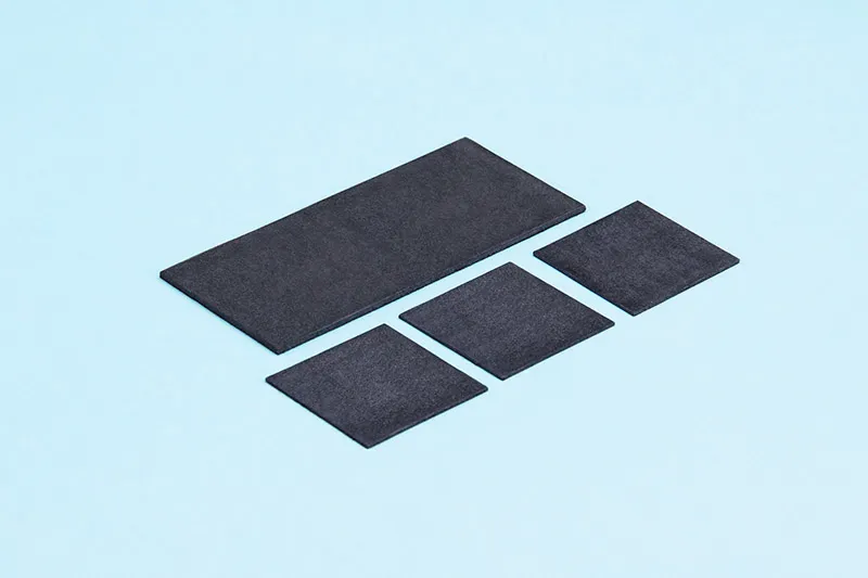
Carbon fiber is electrically conductive, and loose fibre shedding at cut edges is a known handling risk. Specify sealed or film-laminated edges, and control die-cutting and debris in the assembly process. As with graphene, isolation must be designed in, not assumed.
Thermally Conductive Epoxy Resin for Structural Bonds
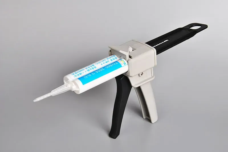
Bonding role
- Structural adhesive provides mechanical strength.
- Controlled bond line thickness limits thermal resistance.
Cooling role
- Higher filler loading improves heat transfer.
- A suitable potting compound can secure nearby parts.
For thermal management in AI server assemblies, Sheen Technology can pair mechanical joining with practical thermal paths.
Polyimide Insulating Film to Protect Sensitive Circuits
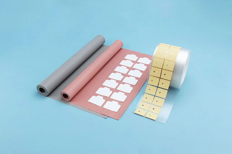
- Electrical protection: Polyimide polymer film delivers high dielectric strength around crowded circuitry.
- Heat endurance: Strong thermal stability supports high temperature operation without adding much thickness.
- Service life: Good electrical insulation strengthens circuit protection and long-term reliability, a key piece of AI server heat control.
TIM selection matrix for AI server interfaces:
| Material | Strong Thermal Direction | Electrically | Thickness (mm) | Select When |
| Phase-change material | Through-plane | Depends on filler | 0.13–0.5 | Flat, clamped interface; lowest resistance target |
| Thermal grease | Through-plane | Depends on filler | - | Thinnest bond line; pump-out risk manageable |
| Vertically aligned graphene pad | Through-plane | Conductive | 0.3–2.0 | High through-plane flux plus coplanarity error |
| Vertically aligned carbon fiber pad | Through-plane | Conductive | 0.3–12.0 | Higher pressure, thicker gap, reworkable |
| Boron nitride pad | Through-plane | Insulating | 0.2–5.0 | Live conductors under the interface |
| Synthetic graphite sheet | In-plane (spreader) | Conductive | 0.06–0.13 (film) | Lateral hotspot spreading, not gap filling |
| Thermally adhesive epoxy | Through-plane | Depends on filler | - | Structural bond plus thermal path |
| Polyimide insulating film | Dielectric barrier | Insulating | 0.2–0.5 | Isolation over graphite / graphene / busbars |
Choosing the right thermal interface material also depends on the interface location, bond-line thickness, heat flux, compression and electrical requirements. For a more detailed comparison of TIM1, TIM1.5 and TIM2 materials for AI processors and HPC cooling, see our AI server TIM selection guide.
5 Steps to Predictive Thermal Monitoring
Predictive monitoring spots cooling trouble while operators still have room to act. For thermal management for AI server systems, connected temperature, pressure, leak, and flow data reveal small changes early. Sheen Technology can bring these signals together, making AI server thermal management more practical day-to-day.
Step 1: Deploy Fiber Optic Temperature Sensors
Place each fiber optic sensor near CPU and GPU hotspots.
- Use optical cable for interference-free thermal sensing.
- Compare server rack trends to catch poor heat dissipation.
This gives thermal management for AI server hardware sharper temperature monitoring without electrical noise.
Step 2: Integrate Digital Pressure Transducers
A pressure transducer adds a useful reality check to liquid cooling. Track coolant pressure across pumps and cold plates; changing pressure reading patterns can expose restrictions before flow stability takes a hit.
That keeps thermal management for AI server operations ahead of trouble.
Step 3: Add Coolant Leak Detection Cable Networks
- Leak early: Route detection cable around couplings and manifolds.
- Pinpoint risk: Connect each moisture sensor to the sensor network for faster coolant spill alerts and better data center safety.
Step 4: Calibrate Mass Flow Meters for Coolant Rates
Calibrate each mass flow meter against the expected coolant rate. Good flow calibration confirms real liquid flow, helping preserve thermal efficiency when cooling demand jumps.
Reliable rates strengthen thermal management for AI server control.
Step 5: Install Redundant Thermocouple Probe Arrays
Build a redundant array around major heat sources.
- Compare each thermocouple probe.
- Map the temperature gradient.
- Flag sensor drift early.
A wider sensor array improves thermal mapping and practical heat management across every AI server.
Thermal Management for AI Server: Adoption Best Practices
Effective thermal management for AI server deployments starts inside the machine, not as a later facility fix. Coordinating AI servers, cooling hardware, fluids, seals, and pumps early keeps AI thermal management practical as rack heat climbs.
Integrate Direct Liquid Cooling Cold Plates Early
Plan direct liquid cooling during the integration phase, while processor location and server architecture can still change.
Align cold plates with high-power processors.
- Keep coolant paths short to reduce thermal resistance.
- Check manifolds and chassis clearances before layouts lock.
Model heat dissipation under peak AI server loads.
- Good contact improves thermal performance and makes thermal management for AI server hardware easier to scale.
Choose Engineered Thermal Fluid for Consistent Viscosity
The thermal fluid has to behave predictably when temperatures shift. Match viscosity stability and thermal conductivity to required flow, then verify that the engineered coolant suits metals, polymers, and tubing.
A suitable heat transfer fluid keeps fluid dynamics manageable across the expected operating temperature range. That helps thermal management for AI server systems avoid nasty surprises when compute demand jumps.
Seal with Fluoropolymer O-Ring Seal Reliability
Build fluid containment around compatible materials:
- Specify a fluoropolymer O-ring for coolant chemistry and temperature.
- Confirm fitting geometry and compression.
Protect seal reliability over service life:
- Check chemical resistance against the selected coolant.
- Review elastomer seals during maintenance.
That practical pairing strengthens leak prevention, a key part of thermal management for AI server operation.
Optimize Packless Centrifugal Pump Placement
Place each packless centrifugal pump around real hydraulic needs:
- Map system layout and distribution piping.
- Calculate required flow rate.
- Limit sharp bends and avoid restrictive paths.
Refine pump placement for dependable coolant circulation.
- Maintain adequate inlet pressure to reduce cavitation risk.
- Support vibration reduction with sensible mounting.
Recheck hydraulic performance at low and peak loads; efficient pumping keeps AI server cooling steady without wasting energy.
Thermal Management for AI Server: Roadmap to Zero Downtime
Effective thermal management for AI server hardware depends on coolant control, early fault signals, and service-friendly connections working together. Sheen Technology brings these cooling functions into practical designs that keep AI servers running with less maintenance fuss.
Automated Coolant Flow Control Valve Adjustments
A responsive control valve links cooling output with actual computing demand, giving thermal management for AI server deployments tighter control without wasting pumping power.
Workload-driven cooling
- A temperature sensor tracks changing chip heat.
- The valve adjusts coolant flow and flow rate as GPU demand rises or falls.
Stable operation
- Fast actuator response supports precise thermal regulation.
- In liquid cooling, this closed-loop approach keeps temperatures in check and cuts unnecessary circulation.
Real-Time Alerts from Digital Pressure Transducers
A pressure transducer turns hydraulic pressure into usable telemetry data, so AI server cooling teams get a quick heads-up when circulation starts behaving oddly.
- System monitoring continuously reads each digital sensor.
- Crossing a defined pressure threshold triggers a real-time alert.
- Maintenance staff can investigate pumps, restrictions, or leak detection signals before cooling performance drops.
That early warning matters. Sheen Technology uses pressure visibility to support more predictable thermal management for AI server infrastructure and reduce avoidable downtime.
Quick Disconnect Coupling for Rapid Maintenance
A quick disconnect makes liquid-loop service quicker while keeping coolant where it belongs.
Faster repairs
- The coupling mechanism simplifies cold-plate or manifold removal.
- A secure pipe fitting supports fluid leakage prevention during servicing.
Better availability
- Hot-swap capability can reduce lengthy shutdown procedures.
- Higher maintenance efficiency protects system uptime, helping AI thermal management stay practical as server density grows.
Sheen Technology develops and manufactures thermal interface materials — vertically aligned graphene pads, boron nitride insulating pads, carbon fiber pads, phase-change materials, gap fillers and synthetic graphite assemblies — supported by die-cutting, film lamination and edge sealing. Application engineers can review your thermal zone map and cold-plate flatness data and propose a candidate stack with datasheet values and test reports.
Contact Sheen Technology for AI Server Interface Support →
Sheen Thermal
Dongguan Sheen Electronic Technology Co., Ltd · Founded in 2008
Manufacturer of thermal interface materials and silicone foam for automotive electronics, energy storage, power electronics, communications and consumer electronics.
Certified
- ISO 9001:2015
- ISO 14001:2015
- IATF 16949:2016
What we supply
- Thermal conductivity Up to 90 W/m·K
- Thickness 0.3–10.0 mm
- Custom & samples Die-cut to drawing, 3–7 days