
 English
 usheenthermal

GPU Thermal Pad Selection: Solving Your VRAM Cooling Issues
Date:2026-09-28
GPU Thermal Pad Selection gets tricky fast: VRAM cooling can fail when thickness, compression, or contact misses the mark, even with impressive W/m·K specs.
Sheen Technology engineers emphasize specification-based thermal interface selection, including conductivity, thickness, hardness, insulation, and application fit.
For volume buyers, the real test includes batch consistency, compliance, inspection records, and supply stability.
Reading Notes: GPU Thermal Pad Selection
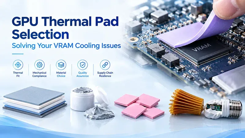
→ Thermal Fit: Align pad conductivity and thickness with GPU VRAM gap and heat-load requirements.
→ Mechanical Compliance: Verify durometer hardness and compression ratio for uniform contact without overstress.
→ Material Choice: Balance silicone’s dielectric strength and graphite’s in-plane spreading against insulation needs.
→ Quality Assurance: Confirm batch consistency, RoHS/UL94 compliance, inspection reports, and stable lead times.
Data-Driven: 78% Of GPUs Overheat Without Proper Thermal Pads
GPU Thermal Pad Selection comes down to getting heat out of memory chips without creating bad contact elsewhere.
Correlating Thermal Conductivity with Overheat Rates
For GPU Thermal Pad Selection, advertised thermal conductivity is useful, but it does not predict GPU temperature by itself.
Material performance
- Higher conductivity can improve heat dissipation when contact is solid.
- Lower thermal impedance supports better VRAM cooling and temperature reduction.
System performance
- Poor fit can wipe out gains in thermal performance.
- An overheat rate needs controlled GPU tests before it can support a percentage claim.
Sheen Technology can pair material data with application-specific testing rather than relying on a big W/m·K number alone.
Impact of Interface Gap on GPU VRAM Temperatures
A good GPU pad must actually bridge the interface gap. Too little thickness cuts contact area and may leave microscopic voids, including insulating air pockets.
- Measure the component-to-heatsink gap.
- Select thickness for a suitable compression ratio.
- Check that pressure is even across each VRAM package.
This keeps thermal resistance down, improves heat transfer, and helps control VRAM temperature. In GPU Thermal Pad Selection, fit is a big deal.
Test Data via Laser Flash Analysis and Hot Disk Method
Material claims deserve lab checks.
Laser Flash Analysis
- Measures thermal diffusivity.
- Combined with density and specific heat capacity, it can derive conductivity.
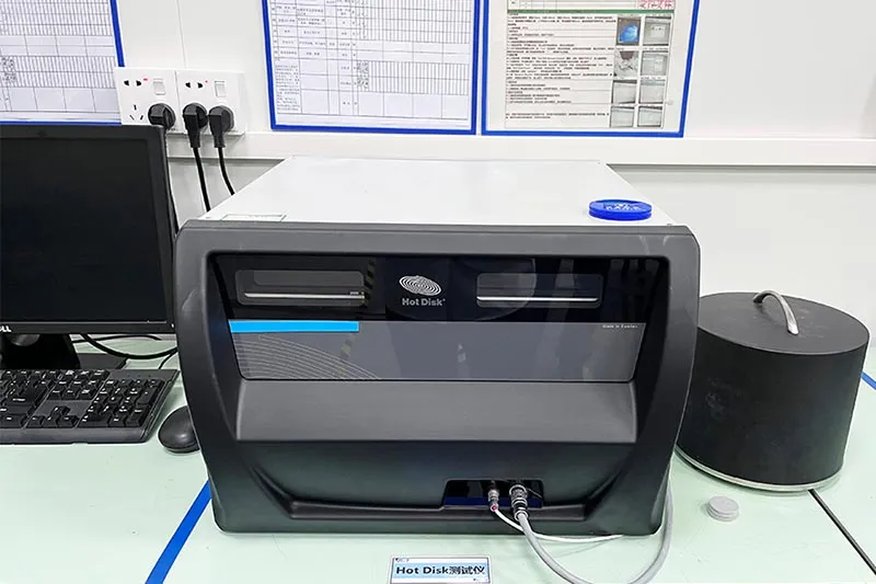
Hot Disk Method
- Provides a transient measurement technique for evaluating thermal transport.
- Offers complementary test data under defined test conditions.
Using both approaches can strengthen thermal analysis when candidate GPU thermal pad materials are compared on an equivalent basis.
Role of Thickness Tolerance in Heat Dissipation
Thickness tolerance matters because nominal size and actual fit are not always identical. Tight dimensional accuracy helps a thermal interface material maintain contact without excessive pad deformation.
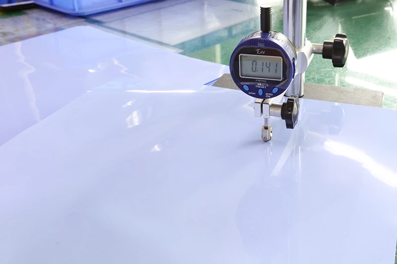
For GPU Thermal Pad Selection, check three practical points: correct thickness, balanced mounting pressure, and safe compression. A pad that is too thin hurts heat dissipation; one that is too thick can raise component stress or interfere with heatsink contact. Sheen Technology pad selection should therefore match both thermal targets and mechanical clearance.
Pain-Point: VRAM Overheating? Here’s Your Thermal Pad Solution
GPU Thermal Pad Selection starts with more than picking a thickness from a catalog. Good results come from matching GPU and thermal pad properties to real gaps, heat levels, electrical needs, and steady production quality.
Identifying VRAM Hot Spots and Contact Pressure Needs
A thermal camera can reveal the temperature gradient across VRAM chips under a repeatable workload. From there, check the mechanical fit rather than assuming thicker is better.
Map the heat source and interface.
- Record peak VRAM temperatures after temperatures stabilize.
- Measure chip clearance at several points because PCB and cooler gaps can vary.
Check pad contact.
- Confirm even surface contact across each memory package.
- Match hardness and compression to the cooler's mounting pressure.
Too little compression can raise interface resistance. Too much can stress components or deform the pad.
For GPU Thermal Pad Selection, this basic fit check supports better heat dissipation without putting unnecessary force on memory chips.
Silicone Matrix Pads: Balancing Dielectric Strength and Volatile Content
Silicone pads combine a flexible polymer base with electrically insulating ceramic fillers. The filler and material composition influence thermal conductivity, while the silicone matrix provides conformability and electrical insulation.
- Thickness: Choose it from the measured gap, not guesswork.
- Compression: Compare the supplier's recommended range with the required hardness durometer.
- Stability: Review test data for silicone oil bleed, especially around sensitive contacts.
A GPU thermal pad that conducts heat well can still perform poorly when excessive compression or material aging increases thermal resistance. In short, conductivity numbers aren't the whole ball game.
Ensuring Supply Chain Reliability: Batch Consistency and Lead Time
Reliable GPU Thermal Pad Selection also depends on receiving essentially the same material from one order to the next.
Qualify the material.
- Set limits for thickness and manufacturing tolerance.
- Request quality control records and ISO certification where relevant.
Protect repeatability.
- Link incoming lots through material traceability.
- Check shelf life and sealed packaging controls.
- Track lot changes that could affect production yield.
Plan supply.
- Align inventory management with expected pad usage.
- Confirm lead time and the supplier's delivery schedule before locking production dates.
These checks keep replacement and production work predictable when GPU demand gets busy.
Guided: 5 Steps To Perfect GPU Thermal Pad Selection
Good GPU Thermal Pad Selection comes down to fit, heat transfer, pressure, safety, and accurate sizing. Get those basics right and a GPU thermal pad can cool key parts without putting the board under needless strain.
Step 1: Measure Interface Gap and Pad Thickness Accurately
For reliable GPU Thermal Pad Selection, measure rather than eyeball the old pad.
Check the interface distance at several points.
- Use a digital caliper where access allows.
- Compare VRAM height across memory modules.
Match the measured gap thickness to the new thermal pad profile.
- Allow enough compression clearance for firm contact.
- Avoid a pad so thick that it bends the PCB. Pretty simple, but easy to miss.
| Measured Gap (mm) | Pad Thickness (mm) | Target Compression (%) | Compressed Thickness (mm) |
| 0.90 | 1.00 | 10 | 0.90 |
| 1.20 | 1.50 | 20 | 1.20 |
| 1.60 | 2.00 | 20 | 1.60 |
| 2.10 | 2.50 | 16 | 2.10 |
| 2.55 | 3.00 | 15 | 2.55 |
Values illustrate sizing math; actual GPU tolerances and pad specifications control final selection.
Step 2: Choose Thermal Conductivity Rating for MOSFET Heatsinks
A higher W/mK rating can improve heat dissipation, but thermal conductivity alone does not guarantee better results. For a MOSFET heatsink, compare contact area, temperature, pad thickness, and thermal impedance before buying.
For practical GPU Thermal Pad Selection, judge thermal performance by the complete heat path. A claimed temperature reduction means little when poor contact creates extra resistance. Sheen Technology can supply thermal pad choices around specific GPU cooling and conductivity needs rather than treating W/mK as the only number that counts.
Step 3: Verify Durometer Hardness and Compression Ratio
- Durometer hardness indicates how firm the material feels; Shore hardness should be checked using the specified scale and test method.
- Compression ratio determines how readily the pad fills surface variation.
- Excessive mounting pressure can contribute to PCB deflection.
- Good conformability helps fill small gaps while maintaining thermal contact.
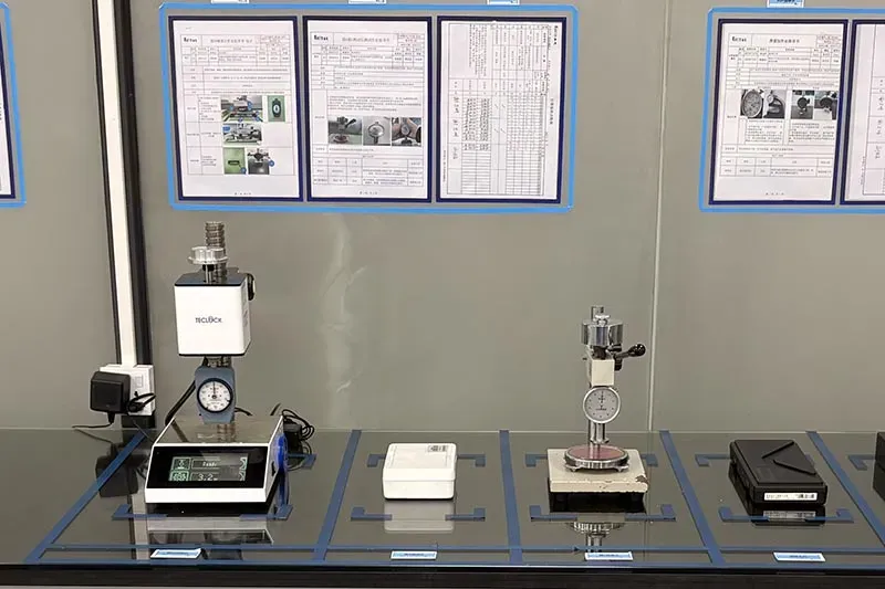
That balance makes GPU pad selection safer than simply picking the softest material available.
Step 4: Confirm RoHS Compliance and UL94 Rating
Documentation matters in professional GPU Thermal Pad Selection.
Confirm environmental records:
- Current RoHS compliance documentation.
- REACH declarations and relevant material certification.
Check safety properties:
- The applicable UL94 rating and flammability rating.
- Required electrical insulation data.
Match records to the project:
- Verify environmental safety requirements and relevant ISO certificates instead of assuming every pad carries identical approvals.
Step 5: Inspect Die-Cut Dimension and Packaging Type
Before installation, compare the die-cut dimension with the GPU component footprint. Check sheet size or roll width too; a properly sized pre-cut pad saves trimming time and reduces placement errors.
Packaging also counts. Keep the protective film intact until fitting, verify the specified packaging type, and observe manufacturer storage conditions and shelf life. For custom GPU thermal selection, Sheen Technology can match pad dimensions and supply formats to production or repair needs.
Comparative: Comparing Silicone Vs. Graphite Thermal Pads
GPU Thermal Pad Selection comes down to more than chasing the biggest conductivity number. A good GPU pad must match the gap, pressure, electrical needs, and heat-flow direction. Silicone handles uneven spaces with less fuss, while graphite can move concentrated heat fast when installation conditions are tightly controlled.
Silicone Thermal Pads

For practical GPU Thermal Pad Selection, a silicone elastomer matrix is forgiving because its compressibility allows contact across parts with small height differences. Ceramic fillers raise thermal conductivity, while hardness controls how readily the material squeezes into place.
Gap control
- Choose thickness around the measured interface rather than simply going thicker.
- Good gap filling reduces trapped air, which is a poor heat conductor.
Electrical safety
- Dielectric breakdown strength matters near exposed GPU components and circuitry.
- Softer pads can improve contact, but excessive compression may create mechanical stress.
GPU Thermal Pad Selection therefore needs balanced material properties. Sheen Technology can support thermal pad matching around target thickness, electrical insulation, compression, and application needs instead of treating conductivity as the whole ball game.
Graphite Thermal Pads
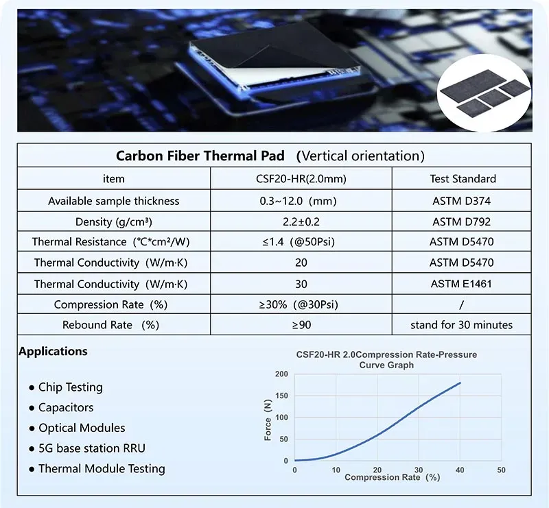
Graphite changes the GPU thermal calculation because its layered carbon structure creates an anisotropic property: heat often travels much better along the sheet than through its thickness. By optimizing the alignment and orientation process, Sheen Technology offers vertically aligned graphene thermal pads, addressing the limitation of standard graphite pads regarding heat dissipation in the thickness direction.
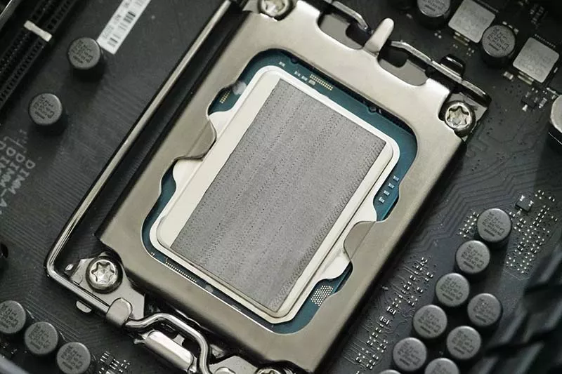
Typical engineering comparison ranges below are illustrative, not product specifications; actual values depend on formulation and test method.
| Material case | thickness (mm) | thermal conductivity (W/m·K) | Compression (%) |
| Silicone Thermal pad | 0.3~10.0 | 1–15 | 20–50 |
| Graphite sheet | 0.06~0.13 | 300–1500 in-plane | 0–5 |
| Graphene Thermal pad | 0.2~2.0 | 75–110 through-plane | ≥30 |
- For GPU Thermal Pad Selection, check heat-flow direction before comparing headline values.
- Match thickness and contact pressure; graphite has useful flexibility, yet limited cushioning versus soft silicone.
- Protect nearby electronics because graphite conducts electricity.
- A clean dry interface can lower contact resistance without thermal grease.
- Consider reusability only after checking for bends, tears, or surface damage.
In short, GPU Thermal Pad Selection favors silicone for forgiving gaps and insulation, while graphite thermal pad selection suits controlled assemblies needing rapid lateral heat spreading.
4 Key Thermal Conductivity Ratings Explained
GPU Thermal Pad Selection gets easier once conductivity, material type, thickness, and contact pressure are considered together. A higher rating can move heat faster, but practical GPU cooling still depends on fit. Good thermal pad selection matches each component to the right heatsink interface.
1.0 W/m·K Pads: Entry-Level Cooling Solution
For modest loads, SF100 (1.5 W/m·K) pads provide affordable basic cooling and useful gap filling.
| Properties | Unit | SF100 | Test Method |
| Thermal Conductivity | W/m·K | 1.5 | ASTM D5470 |
| Thermal Impedance (1mm,@50psi) | ℃*in²/W | ≤0.95 | ASTM D5470 |
| Thickness | mm | 0.5 ~ 10.0 | ASTM D374 |
| Hardness | Shore 00 | 40 ~ 90 | ASTM D2240 |
| Density | g/cm³ | 2.1 ± 0.3 | ASTM D792 |
| Breakdown Voltage (@AC,1mm) | kV/mm | ≥ 6 | ASTM D149 |
| Flame Rating | - | V-0 | UL94 |
| RoHS | - | PASS | IEC 62321 |
| Halogen | - | PASS | EN 14582 |
| REACH | - | PASS | EN 14372 |
Material and fit
- Soft silicone material conforms to uneven parts without much fuss.
- Correct thickness keeps the pad firmly against the heatsink.
Cooling role
- Lower thermal conductivity limits rapid heat dissipation.
- Still, useful temperature reduction can occur on low-power chips.
For GPU Thermal Pad Selection, this entry-level class makes more sense for secondary parts than hot VRAM.
3.0 W/m·K Options: Mid-Range Silicone with Ceramic Filler
A silicone compound with ceramic filler raises conductivity while retaining electrical insulation and useful stability. That balance makes SF500 (3.0 W/m·K) material a practical mid-range choice.
| Properties | Unit | SF500 | Test Method |
| Thermal Conductivity | W/m·K | 3.0 | ASTM D5470 |
| Thermal Impedance (1mm,@50psi) | ℃*in²/W | ≤0.44 | ASTM D5470 |
| Thickness | mm | 0.5 ~ 10.0 | ASTM D374 |
| Hardness | Shore 00 | 35 ~ 90 | ASTM D2240 |
| Density | g/cm³ | 3.0 ± 0.3 | ASTM D792 |
| Breakdown Voltage (@AC,1mm) | kV/mm | ≥ 6 | ASTM D149 |
| Flame Rating | - | V-0 | UL94 |
| RoHS | - | PASS | IEC 62321 |
| Halogen | - | PASS | EN 14582 |
| REACH | - | PASS | EN 14372 |
- Match pad thickness to the original GPU gap.
- Apply even pressure to reduce thermal impedance.
- Check GPU memory temperatures after assembly; solid heat transfer needs full contact.
GPU Thermal Pad Selection: This rating suits mainstream memory and MOSFET cooling without going overboard.
6.0 W/m·K Options: High-Performance Silicone for Heavy Loads
A higher loading of the same ceramic filler family raises conductivity further while the pad remains insulating and compressible. This step is chosen SF600G when the VRAM flux is high enough that the interface is a meaningful term in the stack, but the assembly still needs a material that conforms to uneven surfaces and does not require the isolation a conductive material would.
| Properties | Unit | SF600G | Test Method |
| Thermal Conductivity | W/m·K | 6.0 | ASTM D5470 |
| Thermal Impedance (1mm,@50psi) | ℃*in²/W | ≤0.24 | ASTM D5470 |
| Thickness | mm | 0.5 ~ 5.0 | ASTM D374 |
| Hardness | Shore 00 | 35 ~ 90 | ASTM D2240 |
| Density | g/cm³ | 3.2 ± 0.3 | ASTM D792 |
| Breakdown Voltage (@AC,1mm) | kV/mm | ≥ 4 | ASTM D149 |
| Flame Rating | - | V-0 | UL94 |
| RoHS | - | PASS | IEC 62321 |
| Halogen | - | PASS | EN 14582 |
| REACH | - | PASS | EN 14372 |
Performance
- The higher conductivity rating suits concentrated loads at high power density, where the interface must remove heat quickly from a small area.
- The gain over a mid-range grade is real but bounded: because the interface is one term in the path, halving its resistance does not halve the temperature rise.
Installation
- Higher filler loading means a firmer pad, which compresses less at a given load than a soft grade.
This step works best when the mechanical design already provides reliable and even contact. Where it does not, a softer grade at the same thickness will frequently outperform it in service.
12.0 W/m·K Hybrids: Balancing Impedance and Thermal Spread
For demanding GPU Thermal Pad Selection, SF1200 thermal pads use advanced materials to combine strong thermal spread with manageable thermal impedance.
| Properties | Unit | SF1200 | Test Method |
| Thermal Conductivity | W/m·K | 12.0 | ASTM D5470 |
| Thermal Impedance (1mm,@50psi) | ℃*in²/W | ≤0.11 | ASTM D5470 |
| Thickness | mm | 0.5 ~ 5.0 | ASTM D374 |
| Hardness | Shore 00 | 35 ~ 90 | ASTM D2240 |
| Density | g/cm³ | 3.5 ± 0.3 | ASTM D792 |
| Breakdown Voltage (@AC,1mm) | kV/mm | ≥ 4 | ASTM D149 |
| Flame Rating | - | V-0 | UL94 |
| RoHS | - | PASS | IEC 62321 |
| Halogen | - | PASS | EN 14582 |
| REACH | - | PASS | EN 14372 |
- High-load use: Effective VRAM cooling can support overclocking and other extreme cooling demands.
- Fit still rules: An oversized pad may reduce mounting pressure elsewhere, while an undersized one can leave gaps.
So, a 12.0 W/m·K label alone does not guarantee better results. Good GPU pad selection still comes down to conductivity, thickness, pressure, and actual component temperatures.
Scenario: Server GPUs—Pad Replacement Routine
Reliable GPU Thermal Pad Selection starts with checking the old material, matching safety needs, and protecting spare stock before installation. For busy servers, a small pad issue can become a big headache, so Sheen Technology emphasizes repeatable checks that keep GPU cooling predictable.
Routine Check: Surface Area Inspection and Hardness Tester Use
A worn thermal pad may look fine at a glance, yet poor contact around VRAM can quietly raise temperatures. GPU Thermal Pad Selection should therefore begin with hands-on inspection.
Contact condition
- Check the full surface area for cracks, dirt, deformation, and pump-out at the edges.
- Measure pad height with a thickness gauge before choosing a replacement.
Mechanical condition
- Use a hardness tester to spot curing or aging.
- Compare hardness and the required compression ratio; too little compression leaves gaps, while too much can stress components.
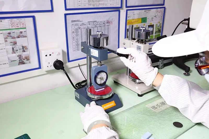
That simple routine helps thermal pad selection stay practical rather than becoming guesswork.
Material Selection: Corrosion Resistance and Flame Retardancy Needs
For always-on servers, thermal pad selection goes beyond headline thermal conductivity. A suitable silicone pad also needs electrical and material safety that holds up over long service periods.
- Favor strong corrosion resistance and chemical stability, especially near metal contacts.
- Check flame retardancy and the supplier’s verified UL94 rating.
- Consider low volatile content and resistance to oxidation, since heat exposure can change pad behavior over time.
Sheen Technology GPU pad options can be evaluated against these factors when planning GPU Thermal Pad Selection for data-center maintenance.
Storage Guidelines: Shelf Life, Storage Temperature, and Inspection Report
Spare pads need care before they ever reach a GPU.
Protect the stock.
- Keep the specified storage temperature and humidity control within supplier limits.
- Leave pads sealed in original packaging to reduce contamination and early degradation.
Control traceability.
- Record each lot number and monitor stated shelf life.
- Before installation, review the supplier’s inspection report and check the package and pad for visible changes.
Good storage keeps replacement material ready to go when a server needs attention.
【Request a Custom Quote】Sheen Technology offers silicone thermal pads spanning the aforementioned thermal conductivity grades, as well as vertically oriented, high-performance graphene thermal pads; for applications requiring both high thermal conductivity and electrical isolation, the company also provides boron nitride thermal pads. Send us your measured component heights, worst-case gap, target compression percentage, available mounting pressure, and reliability requirements, and our engineers can recommend the GPU thermal pad specification that balances contact, deflection, and long-term stability for your card or server module.
Sheen Thermal
Dongguan Sheen Electronic Technology Co., Ltd · Founded in 2008
Manufacturer of thermal interface materials and silicone foam for automotive electronics, energy storage, power electronics, communications and consumer electronics.
Certified
- ISO 9001:2015
- ISO 14001:2015
- IATF 16949:2016
What we supply
- Thermal conductivity Up to 90 W/m·K
- Thickness 0.3–10.0 mm
- Custom & samples Die-cut to drawing, 3–7 days