
 English
 usheenthermal

Solving HBM Thermal Management Challenges in Modern AI Chips
Date:2026-09-28
HBM Thermal Management gets tricky fast: rising AI-chip heat flux can turn one weak material interface into a stubborn hotspot, stressing memory, micro bumps, and package reliability. Cooling hardware alone can’t save the day.
For buyers, thermal conductivity is only part of the deal. Consistency, expansion behavior, processing, quality, and supply all shape production success.
Quick Notes: HBM Thermal Management Essentials
- Ensure high-performance Thermal Interface Material to minimize interfacial Thermal Resistance between HBM and heat spreaders.
- Monitor Underfill Resin Thermal Conductivity and Dispensing Technology to prevent air voids and hotspot formation around Micro Bumps.
- Match Coefficient of Thermal Expansion across silicon, Interposer, Underfill, and Substrate to reduce Thermal Stress and fatigue.
- Consider Micro-Jet Cooling with phase-change–resistant nozzles and verify via Infrared Thermography for targeted hotspot mitigation.
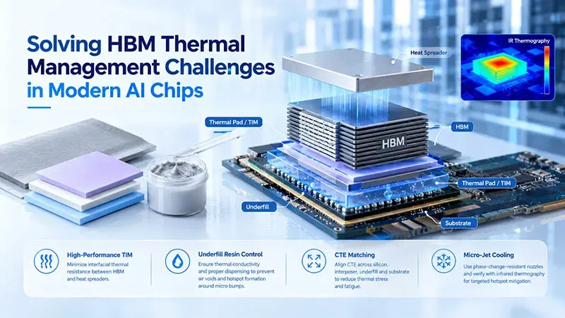
This image was generated with the assistance of AI; it is not a real photograph and is for reference only.
HBM Thermal Management Fundamentals
HBM Thermal Management keeps stacked memory from getting too hot as power rises. Good HBM cooling depends on interfaces, spreaders, package materials, and molding choices working together without adding unwanted stress or thermal bottlenecks.
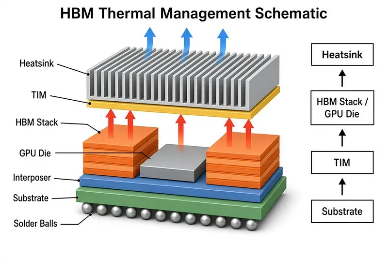
Thermal Interface Material: Bridge Between HBM and Heat Spreader
Thermal path
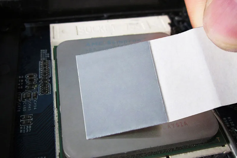
- Thermal interface material acts as a gap filler between HBM and the heat spreader, replacing tiny air pockets.
- Higher thermal conductivity supports faster heat dissipation.
Mechanical fit
- Suitable interface pressure lowers contact resistance without placing excessive force on delicate stacks.
That small interface matters a lot: HBM Thermal Management can lose efficiency when bond lines are thick or uneven.
Graphite Sheet and Copper Heat Spreader Synergy
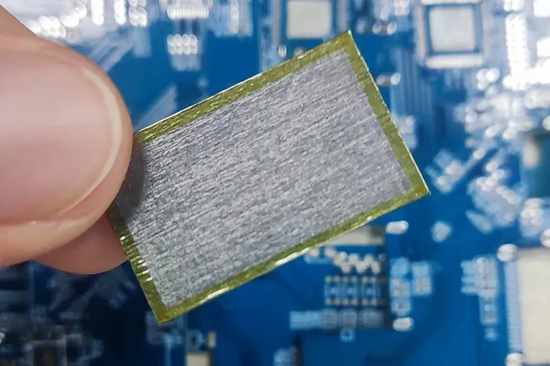
A graphite sheet has strong anisotropic properties, so its in-plane thermal conductivity can move concentrated heat flux sideways fast. Natural-grade graphite typically exhibits thermal conductivity of 300–700 W/m·K, while top-tier synthetic grades can reach nominal values of 1,500–1,900 W/m·K; however, thermal conductivity in the thickness direction (vertical direction) is generally low. The vertically oriented graphene thermal pad introduced by Sheen Technology is a flexible gap-filling material with a thermal conductivity of up to 110 W/m·K, enabling it to conduct heat along the thickness axis while conforming to contact surfaces.
In contrast, graphite sheets primarily conduct heat laterally (in-plane) and lack conformability. If the design requires a flexible bonding material, a graphene thermal pad should be selected; if lateral heat spreading above a heat-generating chip is required, a graphite sheet is the appropriate choice.
Glass Transition Temperature and Specific Heat Capacity Essentials
Material behavior
- Glass transition temperature marks the range where a polymer matrix shifts toward softer behavior.
- Specific heat capacity describes the energy needed to raise its temperature.
Package response
- Enthalpy influences transient heat storage.
- Thermal stability helps preserve the intended material phase during HBM Thermal Management cycles.
- Excess heat can accelerate thermal degradation.
These properties help engineers judge how packaging responds to short power bursts and repeated heating.
Compression Molding Process for HBM Substrate Integration
Good compression molding supports tight packaging integration around the HBM substrate.
- Apply thermosetting resin around package features.
- Control pressure so encapsulation reaches narrow spaces.
- Manage temperature and cure time to limit void formation.
- Cool carefully because mold shrinkage can drive warpage and stress.
Done well, the process protects fine interconnects while giving HBM Thermal Management a stable package foundation.
3 Reasons HBM Thermal Management Fails
HBM Thermal Management gets tricky because heat must escape from tightly stacked memory while tiny connections remain mechanically stable. In AI accelerators, HBM heat dissipation depends heavily on what happens beneath and between dies. Poor material choices, trapped air, or expansion mismatch can quietly raise temperatures and damage connections, so these three failure points deserve close attention during package design.
Poor Thermal Conductivity of Underfill Resin
HBM Thermal Management can suffer when the polymer matrix around micro bumps acts like insulation material rather than a heat path.
Material behavior
- Low thermal conductivity raises local thermal resistance.
- Adding silica particles or another resin filler can improve heat transfer.
Package impact
- Restricted heat dissipation encourages hotspots near stacked HBM.
- Higher junction temperatures can cut performance and long-term reliability.
The catch is simple: filler loading must improve thermal flow without making resin too difficult to process.
Inadequate Dispensing Technology Leading to Air Voids
Tiny air voids can seriously undermine HBM Thermal Management because trapped gas conducts heat poorly.
- During the dispensing process, unsuitable viscosity limits flow through narrow bump gaps.
- Excessive or unstable nozzle pressure may introduce micro-bubbles instead of removing them.
- Incomplete filling leaves interface defects, especially across dense TSV packages.
Careful flow control, vacuum assistance where suitable, cure settings, and inspection help underfill reach tight spaces. In short, good coverage matters just as much as the resin recipe.
Mismatched Coefficient of Thermal Expansion Causing Thermal Stress
Silicon, underfill, interposer, and substrate do not expand equally as temperature changes.
Expansion mismatch
- Different thermal expansion coefficient values create structural strain.
- A steep temperature gradient can increase local thermal stress.
Repeated cycling
- Stress may cause warpage.
- Over time, mechanical fatigue can weaken micro bumps and promote delamination.
That mechanical damage can also disrupt HBM thermal paths. Effective thermal management therefore requires compatible materials as well as low operating temperatures.
Overheating HBM? Try Micro-Jet Cooling
AI accelerators pack a lot of heat into tiny spaces, so HBM Thermal Management needs cooling that reacts where heat actually builds up. Micro-jets, smart materials, and careful testing give designers practical ways to control HBM temperatures without going overboard on cooling hardware.
How Micro-Jet Cooling Targets Graphics Processing Unit Hotspots
Micro-jet cooling sends liquid directly toward Hotspots, increasing local convection instead of treating the whole package alike. For HBM Thermal Management, that targeted approach can improve Heat dissipation around High-bandwidth memory and a Graphics processing unit.
Hotspot control
- Close nozzle placement shortens the heat path.
- Higher local flow supports Thermal management when AI chips hit demanding workloads.
That matters because HBM heat can rise quickly during heavy memory traffic.
Optimizing Nozzle Chemistry with Phase Change Material
Good cooling is not just about pumping harder. Nozzle chemistry must suit the Cooling fluid, while Material science choices help limit corrosion, deposits, and wear.
- Select compatible nozzle materials for reliable Microfluidics.
- Add Phase change material where short heat spikes need buffering.
- Tune fluid flow and PCM placement together, improving Heat transfer and Thermal optimization.
This combined approach helps HBM Thermal Management handle fast power swings without letting temperature shoot up.
Verifying Thermal Performance via Infrared Thermography
Infrared thermography provides a clear Temperature distribution map, making Validation of HBM Thermal Management far less of a guessing game. Thermal imaging can compare baseline and cooled devices, while sensors confirm Heat flux and Thermal performance.
| Testing point | Surface temp (°C) | Thermal resistance (°C/W) |
| Baseline GPU | 92 | 0.38 |
| Jet, low flow | 84 | 0.33 |
| Jet, medium flow | 76 | 0.28 |
| Jet, high flow | 71 | 0.25 |
| Jet + PCM | 69 | 0.23 |
These illustrative engineering values show how Sheen Technology can benchmark HBM cooling designs; actual results depend on chip power, nozzle spacing, flow rate, and test conditions.
【Request a Custom Quote】Fighting HBM hotspots, air voids under the heat spreader, CTE-driven warpage, or transient heat spikes near the GPU? Send us your package stack-up, power map, micro-bump pitch, target interface thickness, and thermal test conditions, and our engineers can recommend the thermal interface materials that keep your HBM thermal management predictable in volume production.
Sheen Thermal
Dongguan Sheen Electronic Technology Co., Ltd · Founded in 2008
Manufacturer of thermal interface materials and silicone foam for automotive electronics, energy storage, power electronics, communications and consumer electronics.
Certified
- ISO 9001:2015
- ISO 14001:2015
- IATF 16949:2016
What we supply
- Thermal conductivity Up to 90 W/m·K
- Thickness 0.3–10.0 mm
- Custom & samples Die-cut to drawing, 3–7 days
LAST:Nothing