
 English
 usheenthermal

How to Choose the Best High-Compressibility Phase Change Thermal Pad
Date:2026-05-28
How to Choose the Best High-Compressibility Phase Change Thermal Pad
As heat loads spike in modern electronics, the High compressibility phase change thermal pad stops being optional and starts saving your margins from costly thermal failures.
Cheap pads look fine on paper, but under pressure, they misbehave—poor contact, pump-out, uneven gaps—quietly driving returns, throttled performance, and production headaches you end up paying for.
Sheen Technology engineers note in 2025 briefs that compressibility and phase stability reduce field failure risk at scale.
Reading Notes: High Compressibility Phase Change Thermal Pad Essentials
➔ Maximized Heat Transfer: Leverages ceramic fillers and graphite for low thermal resistance in CPUs, GPUs, and power semiconductors.
➔ Superior Gap Filling: High compressibility adapts to uneven surfaces under variable pressure, reducing contact resistance.
➔ Long-Term Stability: Silicone-based polymer matrix resists pump-out and dry-out through repeated thermal cycles.
➔ Global Compliance: Meets RoHS, REACH, and halogen-free standards for safe, eco-friendly electronics manufacturing.
Why High Compressibility Phase Change Thermal Pad Matters
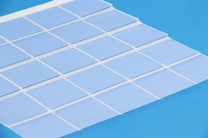
High-power chips run hot, no secret there. This cluster breaks down why a High compressibility phase change thermal pad quietly keeps temperature management steady when devices are pushed hard, daily.
Maximizing Heat Transfer with Low Thermal Resistance
· Heat transfer lives or dies at the interface.· Thermal resistance drops when contact improves.
· Cooling wins feel almost boring when it just works.
Under the hood, a High compressibility phase change thermal pad behaves like a soft bridge. Once heat rises, the interface material shifts phase and spreads, boosting thermal conductivity without squeezing components too hard. That smooth spread tightens surface contact, which sharpens heat dissipation and stabilizes cooling performance.
Nested details matter here:
Material behavior
· Ceramic fillers carry heat fast
· Graphite paths shorten thermal routes
System results
· Lower junction temperature
· Cleaner temperature management under load
A phase change thermal pad keeps the math simple: less resistance, less stress.
Ensuring Reliable Gap Filling Capability under Variable Pressure
· Pressure changes happen.· Boards flex.
· Gaps appear.
A High compressibility phase change thermal pad answers with controlled compressibility, adapting to variable pressure without cracking or sliding. This isn’t magic, just smart conformability that wipes out interface gaps and supports void elimination.
Key interactions stack up:
Mechanical reality
· Uneven heatsinks
· Tolerance drift
Pad response
· Elastic recovery
· Stable surface contact during pressure cycling
The result feels low drama, which is exactly the point.
Enhancing Long-term Reliability in CPUs and GPUs
Thermal cycling wears parts down. Slow. Quiet. Relentless.
A High compressibility phase change thermal pad stays put, resisting pump-out and dry-out, protecting CPU and GPU packages from creeping thermal stress.
Performance doesn’t nosedive overnight. Instead, material stability stretches component lifespan and limits performance degradation across years of heat spikes and cool-downs. Short bursts of gaming or nonstop data crunching both land in the safe zone of long-term reliability.
Meeting RoHS Compliance and Halogen-Free Standards
✓ RoHS compliance✓ Halogen-free chemistry
✓ Environmental standards met without drama
Regulatory trust isn’t optional anymore. A High compressibility phase change thermal pad built with clean polymers avoids hazardous substances, aligns with regulatory requirements, and supports material safety goals tied to eco-friendly manufacturing.
To keep it concrete, here’s how Sheen technology phase change thermal pad typical properties line up:
| Properties | Color | Reinforcement Carrier | Thermal Conductivity | Thermal Impedance (@50psi) | Thickness | Phase Change Temp. |
|---|---|---|---|---|---|---|
| Unit | - | - | W/m·K | ℃*in2/W | mm | ℃ |
| SP205A-30 | Gray | - | 3.0 | 0.05 | 0.2 | 45 ~ 55 |
| SP205A-35 | Gray | - | 3.5 | 0.04 | 0.2 | 45 ~ 55 |
| SP205A-40 | Gray | - | 4.0 | 0.03 | 0.2 | 45 ~ 55 |
| SP205A-50 | Gray | - | 5.0 | 0.02 | 0.3 | 45 ~ 55 |
| SP205A-60 | Gray | - | 6.0 | 0.015 | 0.3 | 45 ~ 55 |
| SP205A-AL-40 | Green/Gray | Aluminum Foil | 4.0 | 0.06 | 0.18 | 50 ~ 60 |
| SP350P | Green | Polyimide | 1.8 | 0.4 (30psi) | 0.13 ~ 0.5 | 45 ~ 55 |
| Test Method | Visual | - | ASTM D5470 | ASTM D5470 | ASTM D751 | ASTM D3418 |
Quiet compliance. Solid numbers. That’s the appeal of a modern High compressibility phase change thermal pad, or simply, a dependable PCM thermal pad that plays nice with global rules.
Need a closer match for your project? Browse these related application pages to see where high compressibility phase change thermal pads are used in real systems.
High Compressibility Phase Change Thermal Pad: 4 Key Specs
High compressibility phase change thermal pad choices can feel like gear shopping with a stopwatch running. This cluster keeps it simple: the four specs that change real-world temps, not just datasheets. You’ll see how a high compressibility phase change thermal pad behaves once clamped down, warmed up, and cycled for months, including what Sheen Technology tunes for day-to-day builds.
Thermal Conductivity (W/m·K) and Ceramic Fillers
A high compressibility phase change thermal pad lives or dies by thermal conductivity and how its fillers pack inside the material at the interface.
Heat transfer basics
· If the polymer matrix is too “soft” without enough loading, you get a comfy fit but weak throughput.
· If loading is too high, the pad can turn stiff and lose contact where it counts.
Ceramic filler choices (why they matter)
· Boron nitride-style ceramics can push W/mK up while staying electrically safer than metal-loaded options.
· Particle shape matters; plate-like fillers can form better pathways, but only if the pad still compresses cleanly.
What to sanity-check for performance
· Ask for conductivity reported at test pressure, not just a headline number.
· Confirm the pad is meant for your mounting force; Sheen Technology typically frames specs around realistic clamp loads for devices using a high compressibility phase change thermal pad.
Compressibility Rate Influencing Contact Resistance
With a high compressibility phase change thermal pad, compressibility is the difference between “pretty good on paper” and “nice, stable temps.” The pad has to deform enough to fill a gap, yet not spring back so hard it creates micro-voids at the surface.
Quick checks
· Clamp pressure: too low and contact resistance stays high; too high and the pad can over-squeeze and thin out.
· Real stack-up: warped lids, tilted heatsinks, uneven screws—this is where deformation earns its keep.
· Outcome: better conformity cuts thermal resistance at the interface, which is exactly why builders reach for a high compressibility phase change thermal pad on GPUs and memory.
· Tiny rule of thumb: if you’re chasing hot spots, prioritize compressibility before obsessing over a small W/mK bump.
Phase Change Temperature Aligned with Operating Range
A high compressibility phase change thermal pad isn’t just “soft”; it’s designed around phase change behavior so the interface wets out when the device gets to its normal operating range.
Match the temperature window
· If the melting point (or softening point) is too high, it stays waxy and never spreads.
· If it’s too low, it can overflow early in the thermal cycle and thin out.
What “aligned” looks like in practice
· Your device reaches the transition zone during typical use, not only during stress tests.
· The solid-to-solid-liquid shift improves wetting without turning the pad into a mess.
Picking for the application
· Laptops like lower activation because airflow and headroom are tight.
· Workstations can tolerate a higher transition if mounting is strong and steady.
If you’ve ever swapped to a PCM pad and seen temps drop after the first warm-up, that’s the phase change doing its job—classic high compressibility phase change thermal pad behavior, and Sheen Technology designs around that ramp-in.
Thermal Impedance and Pump-out Resistance
Low thermal impedance is the goal, but the long game is pump-out control; a high compressibility phase change thermal pad that creeps away under cycling will lose performance even if its lab numbers looked sweet.
| Pad scenario | Clamp load (psi) | Bulk thermal impedance (°C·cm²/W) | Pump-out mass loss after 500 cycles (%) |
| PCM pad A (ceramic-filled) | 20 | 0.18 | 1.2 |
| PCM pad B (higher compressibility) | 20 | 0.20 | 0.8 |
| PCM pad C (softer, low filler) | 20 | 0.27 | 3.5 |
Reliability signals to look for
· Lower mass loss implies better long-term stability and less voiding at the interface.
· Watch for degradation notes: oil bleed, dry-out, or brittle edges after cycling.
Practical take
· A slightly higher impedance pad can win if it resists pump-out and stays consistent.
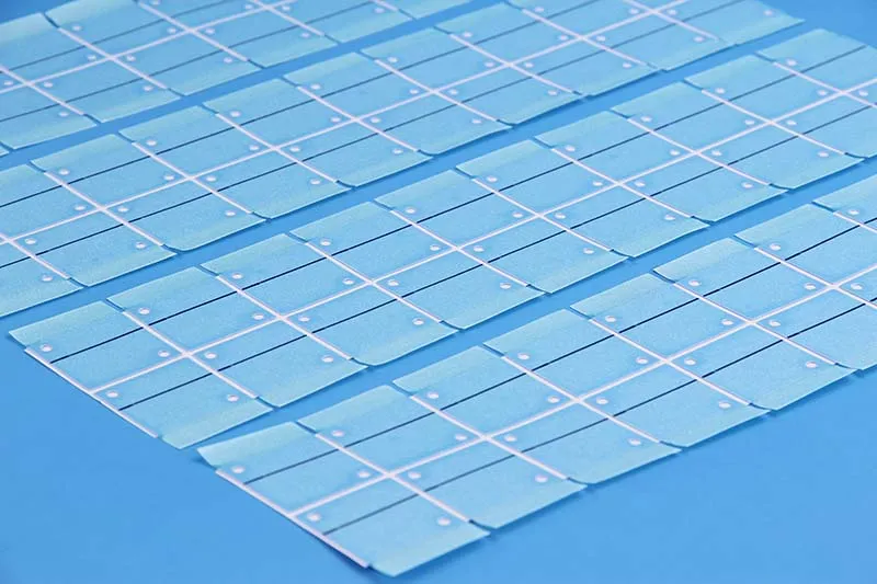
Sheen technology SP205A-60 phase change thermal sheet Reliability Test Report
| Test Items | Test Conditions | Test Equipment |
| High-Temperature Aging | 100℃,1000H | Precision Oven |
| Constant Temperature & Humidity | 85℃、85%RH,1000H | Constant Temperature & Humidity Chamber |
| Thermal Shock | -20℃~80℃,1000H | Constant Temperature & Humidity Chamber |
Criteria for Judging Test Results
| Performance Parameter | Initial Value | Acceptance Criteria |
| Thermal Conductivity(W/m*K) | 6.07 | ±30% |
| Thermal Resistance(℃*in²/W,@10 psi) | 0.082 | ±40% |
| Appearance | Smooth surface, uniform color | No abnormalities (e.g., powdering, discoloration) |
High-Temperature Aging Test Results
| High-Temperature Aging Test Record Sheet | |||||||||
| Aging Time | H | 0 | 200 | 400 | 600 | 800 | 1000 | Change | Assessment |
| Thermal Conductivity | W/m*k | 6.07 | 5.74 | 5.45 | 5.25 | 5.08 | 5.00 | -17.6% | OK |
| Thermal Resistance | ℃*in²/W,@10 psi | 0.082 | 0.084 | 0.089 | 0.095 | 0.102 | 0.107 | +30.5% | OK |
| Appearance | / | No change | No change | No change | No change | Slightly yellow | Slightly yellow | Slightly yellow | OK |
Constant Temperature and Humidity Test Results
| Constant Temperature and Humidity Test Record Sheet | |||||||||
| Aging Time | H | 0 | 200 | 400 | 600 | 800 | 1000 | Change | Assessment |
| Thermal Conductivity | W/m*k | 6.07 | 5.81 | 5.50 | 5.31 | 5.22 | 5.09 | -16.1% | OK |
| Thermal Resistance | ℃*in²/W,@10 psi | 0.082 | 0.090 | 0.094 | 0.098 | 0.101 | 0.105 | +28.0% | OK |
| Appearance | / | No change | No change | No change | No change | Slightly yellow | Slightly yellow | Slightly yellow | OK |
Thermal Shock Test Results
| Thermal Shock Test Record Sheet | |||||||||
| Aging Time | H | 0 | 200 | 400 | 600 | 800 | 1000 | Change | Assessment |
| Thermal Conductivity | W/m*k | 6.07 | 5.72 | 5.50 | 5.33 | 5.18 | 5.07 | -16.5% | OK |
| Thermal Resistance | ℃*in²/W,@10 psi | 0.082 | 0.086 | 0.092 | 0.099 | 0.105 | 0.110 | +34.1% | OK |
| Appearance | / | No change | No change | No change | No change | Slightly yellow | Slightly yellow | Slightly yellow | OK |
Test Conclusion: After aging for 1000 hours under various conditions, the SP205A-60 phase change thermal sheet maintained satisfactory performance with no changes to its appearance. Therefore, the reliability test results are deemed satisfactory.
This is where a high compressibility phase change thermal pad from Sheen Technology tends to focus: repeatable contact after real thermal cycling, not just day-one numbers.
Need exact thermal conductivity, phase change temperature, thickness range, and reliability data before you choose? Download the product datasheets to compare high compressibility phase change thermal pad options.
4 Steps to Install a Thermal Pad Properly
If you want lower temps without the drama, treat a High compressibility phase change thermal pad like a precision part, not a sticker. A little care on surface prep, cut dimensions, and final checks keeps heat moving and hotspots quiet. This run-through fits CPUs, GPUs, SSDs, and power modules, including builds using Sheen Technology pads.
Step 1: Surface Preparation and Wettability Check
A highly compressible phase change thermal pad can only do its job if the interface starts clean and friendly to contact. Skip this and you’ll chase temps forever.
Cleaning basics
· Remove contamination: dust, oil, old grease, stray fibers.
· Wipe the substrate with lint-free swabs; don’t “re-use” a dirty corner.
Wettability sanity check
· Put a tiny IPA bead on the surface: it should sheet out, not bunch up like it’s scared.
· If it beads, go back to preparation; weak adhesion often starts right here.
Fit preview
· Dry-place the High compressibility phase change thermal pad to confirm it sits flat on the interface with no rocking.
Step 2: Precise Die Cutting to Custom Geometry
Die cutting is where “close enough” turns into a mess, so keep it tight. For a High compressibility phase change thermal pad, clean edges help ensure consistent contact.
· Lock dimensions from CAD or a caliper check; don’t guess the size from photos.
· Pick tooling that matches the job: steel rule for quick turns, hard dies for repeated manufacturing runs.
· Validate accuracy with a test cut: confirm shape alignment to keep-out zones and screw bosses.
· Tip: if the custom geometry wraps around components, add small reliefs so the pad doesn’t buckle.
Step 3: Laminating Adhesive Backing for Secure Fit
A High compressibility phase change thermal pad can creep during assembly if it’s not held down, especially on vertical builds.
Laminating choices
· Use adhesive backing when vibration or cable pull is real; skip it when you need rework-friendly swaps.
Placement control
· Tack one edge, then lie down slowly to avoid trapped air; keep pressure even.
Bond behavior checklist
· Confirm bonding doesn’t lift at corners during installation.
· Re-check attachment after tightening hardware; a “secure fit” should stay secure.
(If you’re sourcing pads at scale, Sheen Technology can supply die-cut parts with laminated backers so your line workers aren’t doing arts-and-crafts.)
Step 4: Verification under Power Semiconductors Load
For power stages, you don’t “install and pray.” You validate the High compressibility phase change thermal pad under thermal load, then keep receipts.
Verification flow
· Baseline: run at steady operation and log case and sink temps.
· Step-load: bump current in stages; watch heat transfer response and settling time.
· Post-run: inspect for pump-out, corner lift, or uneven imprint—simple clues to reliability.
Test log template for power semiconductors (testing + performance)
| Load step | Current (A) | Time (min) | Case temp (°C) | Sink temp (°C) |
| 1 | 10 | 10 | 52 | 41 |
| 2 | 20 | 10 | 63 | 48 |
| 3 | 30 | 10 | 74 | 55 |
| 4 | 40 | 10 | 86 | 62 |
| 5 | 50 | 10 | 98 | 70 |
If the delta keeps widening at higher steps, your pad choice (or clamp) is off; swapping to a high compressibility thermal pad or re-checking flatness often fixes it.
【Request a Custom Quote】 Not sure which high compressibility phase change thermal pad fits your build? Send us your target operating temperature, thickness target, gap size, and application details, and we can help recommend the right thermal solution for your project.
Sheen Thermal
Dongguan Sheen Electronic Technology Co., Ltd · Founded in 2008
Manufacturer of thermal interface materials and silicone foam for automotive electronics, energy storage, power electronics, communications and consumer electronics.
Certified
- ISO 9001:2015
- ISO 14001:2015
- IATF 16949:2016
What we supply
- Thermal conductivity Up to 90 W/m·K
- Thickness 0.3–10.0 mm
- Custom & samples Die-cut to drawing, 3–7 days