
 English
 usheenthermal

Low Thermal Resistance Carbon Fiber Thermal Pad vs Thermal Paste
Date:2026-07-30
Heat is killing your performance, and that low thermal resistance carbon fiber thermal pad might be the quiet fix engineers keep overlooking in plain sight.
Thermal paste has been the go to for years, but it gets messy, inconsistent, and slows production when precision actually matters.
Recent Gartner and IDC research shows demand for reliable, scalable thermal interface materials in manufacturing.
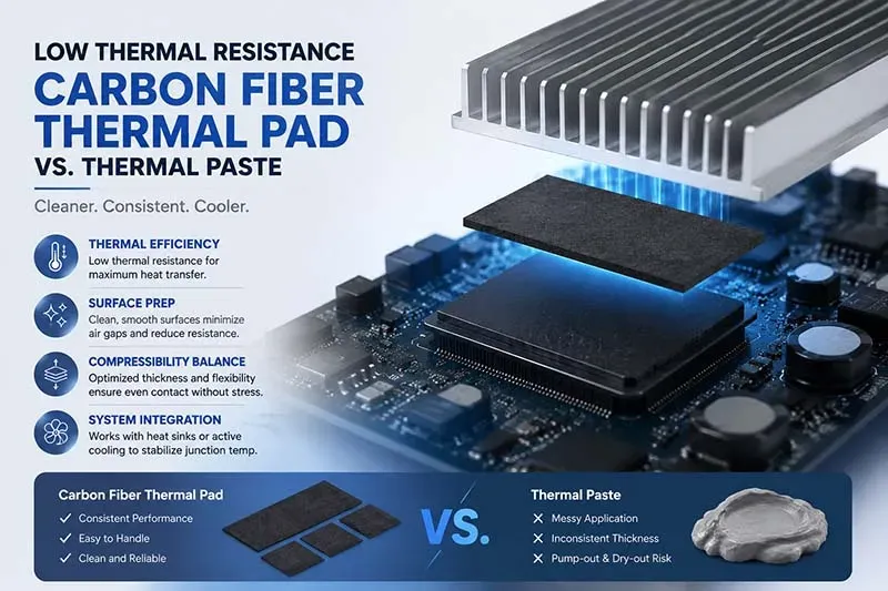
Key Engineering Takeaways: Low Thermal Resistance Carbon Fiber Thermal Interface Pads
→ Thermal Efficiency: Quantify conductivity and interface resistance to ensure maximum heat transfer.
→ Surface Prep: Clean and smooth substrates to eliminate air gaps and lower resistance.
→ Compressibility Balance: Match thickness and flexibility for even contact without overstressing components.
→ System Integration: Pair with heat sinks or active cooling to stabilize junction temperature.
Low Thermal Resistance Carbon Fiber Thermal Pad Efficiency Metrics
A low thermal resistance carbon fiber thermal pad sounds technical, but it’s really about moving heat fast and clean. Break the phrase down—low resistance, carbon fiber, thermal pad—and you get a material built for tight heat paths. From carbon fiber pads to graphite sheets, performance depends on contact, pressure, and structure, not just raw numbers.
Measuring Thermal Conductivity and Interface Resistance
Core evaluation layers:
Material level
- Measure thermal conductivity using steady-state heat flow
- Map thermal properties across fiber orientation
Interface level
- Quantify interface resistance between pad and chip
- Track heat transfer loss at micro gaps
Device integration:
- Apply thermal interface material between CPU and sink
- Record temperature gradient
- Calculate resistance under load
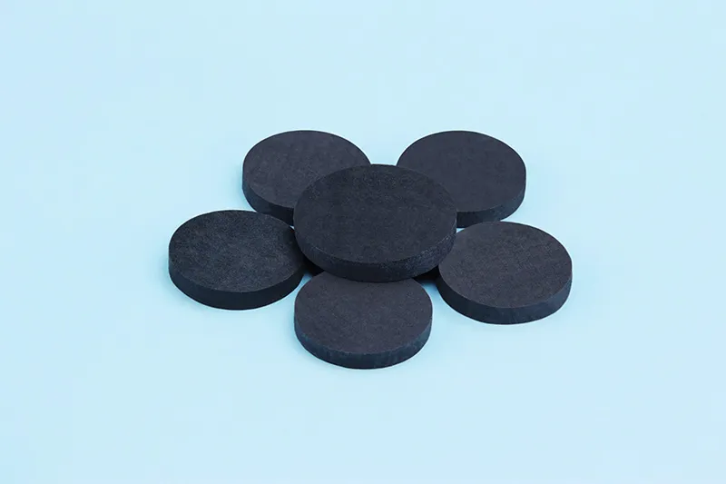
| Product name | Color | Thermal Conductivity | Thermal Impedance (1mm,@20psi) | Thickness | Standard Hardness |
| Unit | - | W/m·K | ℃*in2/W | mm | Shore 00 |
| CSF15 | Black | 15.0 | 0.28 | 0.3 ~ 12.0 | 60~70 |
| CSF20 | Black | 20.0 | 0.18 | 0.3 ~ 12.0 | 60~70 |
| CSF25 | Black | 25.0 | 0.12 | 0.3 ~ 12.0 | 60~70 |
| CSF30 | Black | 30.0 | 0.10 | 0.3 ~ 12.0 | 60~70 |
| CSF35 | Black | 35.0 | 0.09 | 0.3 ~ 12.0 | 60~70 |
| CSF40 | Black | 40.0 | 0.08 | 0.3 ~ 12.0 | 60~70 |
| CSF45 | Black | 45.0 | 0.07 | 0.3 ~ 12.0 | 60~70 |
| Test Method | Visual | ASTM D5470 | ASTM D5470 | ASTM D374 | ASTM D2240 |
Carbon fiber TIM thermal conductivity is typically characterized by ASTM D5470 (steady-state) for through-plane values. In-plane conductivity (relevant to anisotropic carbon fiber structures) may require supplementary laser flash or transient plane source methods. Sheen Technology provides both through-plane and in-plane conductivity data for its carbon fiber pad products.
Assessing Surface Roughness Impact on Heat Dissipation
Surface texture isn’t cosmetic—it drives thermal contact.
Small changes matter:
- smoother surfaces → larger contact area
- rough peaks → trapped air → weaker heat dissipation
Key influences
- surface roughness alters heat transfer coefficient
- surface morphology defines real vs. apparent contact
“Interface quality now contributes up to 40% of total thermal resistance in compact electronics,” notes a 2025 IDTechEx thermal materials update.
A well-made carbon fiber thermal pad reduces those gaps without needing extreme pressure.
Evaluating Compressibility for Optimal Contact Pressure
- Measure compressibility under incremental load
- Track deformation and recovery
- Match contact pressure to chip tolerance
- Confirm optimal contact without die stress
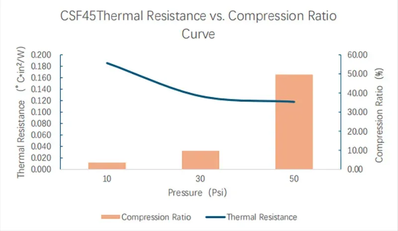
Sheen Technology CSF45 Thermal Resistance Compression Test:
Test conditions:
| Test items | Test conditions | Test equipment | Test Standards |
| Compression Ratio | 25*25 | Compression and Rebound Tester | / |
| Thermal resistance | 10/30/50psi | LW-9389 | ASTM D5470 |
Test results:
| Pressure(Psi) | 10 Psi | 30 Psi | 50 Psi |
| Compression Ratio(%) | 3.56 | 9.74 | 49.71 |
| Thermal resistance(°C·in²/W) | 0.185 | 0.128 | 0.118 |
Short take:
- Soft pad fills gaps.
- Too soft? performance drops.
- Too stiff? risk damage.
A low thermal resistance carbon fiber thermal pad balances mechanical properties and gap filling, especially in uneven assemblies.
Comparing Thermal Impedance Across Composite Materials
Material families:
- Carbon nanotube networks: low thermal impedance, directional flow
- Resin-filled composites: stable, moderate thermal resistance
- Anisotropic graphite: strong planar heat flow, weaker vertical
Performance comparison stack:
- Thickness → thinner reduces path length
- Density → higher improves thermal performance
- Temperature range → stability defines material properties
Across these, a low thermal resistance carbon fiber thermal pad keeps showing up as a practical middle ground—high efficiency, manageable cost, and reliable performance across real-world builds.
4-Step Guide To Applying Carbon Fiber Thermal Pad
Getting a low thermal resistance carbon fiber thermal pad to actually perform isn’t just plug-and-play. Small prep choices swing big thermal results, so this guide walks through practical moves that keep contact tight and heat flow smooth.
Surface Preparation: Cleaning Substrate and Heat Sink
A clean interface makes or breaks a low thermal resistance carbon fiber thermal pad. Any residue or contaminants sitting on the surface will spike thermal impedance.
Focus points:
- Remove contaminants from substrate and heat sink
- Use lint-free wipes during cleaning
- Inspect surface preparation under light
Chemical pass:
- Isopropyl wipe on substrate
- Dry sweep on heat sink
- Final dust check for micro residue
A well-prepped surface lets the carbon fiber thermal pad low thermal resistance behavior show up clearly, instead of getting blocked by invisible grime.
Precision Alignment of Pad Thickness and Density
Getting thermal pad thickness and density right is less guesswork, more matching real gap and pressure conditions.
Key alignment factors:
- Thickness vs measured gap
- Density vs mounting pressure
- Even contact across chips
| Test Item | CSF20-HR | ||
| Density(g/cm³) | 2.230 | 2.119 | 2.095 |
 | 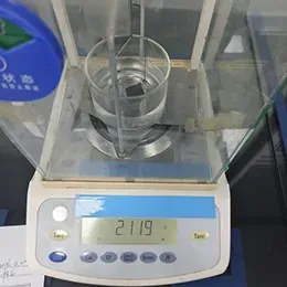 | 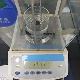 | |
Gap mapping
- Measure corner variance
- Note compression zones
Pad selection
- Low compression → higher density
- High compression → moderate density
Using a low thermal resistance carbon fiber thermal pad from Sheen Technology helps maintain stable contact, especially in uneven assemblies.
Lamination and Curing for Mechanical Strength
This stage locks in adhesion, boosts mechanical strength, and keeps the bond stable during heat swings.
Process layering:
- Apply pressure
- Control temperature
- Allow full curing
Data snapshot:
| Parameter | Low Range | Optimal | High Range |
|---|---|---|---|
| Pressure (kPa) | 50 | 120 | 200 |
| Temperature (°C) | 25 | 80 | 120 |
| Curing Time (min) | 5 | 20 | 45 |
| Adhesion Strength (MPa) | 0.5 | 1.2 | 2.0 |
A properly cured low thermal resistance carbon fiber thermal pad resists pump-out and keeps durability intact over long cycles.
Post-Application Testing of Junction Temperature Drop
Now comes proof. You’re checking if the low thermal resistance carbon fiber thermal pad actually delivers a measurable temperature drop.
Validation flow:
- Sensor placement near junction temperature
- Baseline vs post-application measurement
- Compare thermal performance
Testing layers
- Static load:Record steady heat transfer
- Dynamic load:Track fluctuation stability
- Long-run :Confirm sustained validation
A solid install—especially with Sheen Technology materials—typically shows a clear junction temperature reduction within minutes. If not, revisit contact and surface prep; that’s usually where things slipped.
Low Thermal Resistance Carbon Fiber Thermal Pad For FPGA Cooling
Keeping high-speed chips cool isn’t just a nice-to-have—it’s survival. A low thermal resistance carbon fiber thermal pad bridges the tiny gap between heat sources and cooling hardware, helping systems stay stable under pressure. With tighter layouts and rising power, smarter thermal interface choices make a real difference.
Compatibility with High-Density Integrated Circuits
Core fit with integrated circuits
- Supports high-density layouts without crowding
- Matches varied package types including BGA and fine-pitch FPGA
- Maintains electrical insulation while enabling heat flow
Material behavior
- Flexible thermal interface material reduces mechanical stress
- Stable against encapsulants, protecting device reliability
Practical integration
- Works as a low thermal resistance pad in compact stacks
- Sheen Technology designs carbon fiber pad options tuned for tight tolerances
Short note: a carbon fiber thermal pad with low resistance helps avoid micro-gap hotspots that sneak into dense boards.
Managing FPGA Junction Temperature Through Enhanced Conductivity
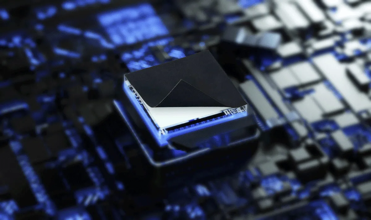
A carbon fiber TIM improves heat transfer right where it counts—the die interface.
Quick hits:
- boosts thermal conductivity
- lowers thermal resistance
- steadies FPGA junction temperature
- During heavy power dissipation, heat spreads fast through the carbon fiber matrix.
- The pad keeps contact uniform, improving cooling performance.
- Result: tighter thermal management margins, fewer throttling events.
Small segments: cooler cores, quieter systems, longer life. Sheen Technology pairs graphene-enhanced options for even faster heat flow.
Integrating Pad with Active Cooling Systems and Heat Sinks
Step-by-step flow using a oriented fiber pad:
- Prep the surface, Clean interfaces to ensure a reliable thermal interface.
- Place the pad, Align for full coverage; avoid overlap on components.
- Apply mounting pressure, Even force improves contact and reduces air gaps.
- Attach heat sinks or active cooling, Fans or liquid loops amplify heat dissipation.
- Validate in system design, Check temps under load; tune thickness if needed.
Modern FPGAs (Xilinx Versal, Intel Agilex) with integrated AI engines and high-speed transceivers exhibit non-uniform heat distribution across the die. Carbon fiber pads with anisotropic thermal conductivity can be oriented to preferentially conduct heat from hotspot regions toward the primary heatsink contact zone. Sheen Technology offers orientation-specified pad configurations for FPGA packages with documented hotspot mitigation.
→ Request Carbon Fiber Pad Evaluation Samples + Application Support
Sheen Thermal
Dongguan Sheen Electronic Technology Co., Ltd · Founded in 2008
Manufacturer of thermal interface materials and silicone foam for automotive electronics, energy storage, power electronics, communications and consumer electronics.
Certified
- ISO 9001:2015
- ISO 14001:2015
- IATF 16949:2016
What we supply
- Thermal conductivity Up to 90 W/m·K
- Thickness 0.3–10.0 mm
- Custom & samples Die-cut to drawing, 3–7 days