
 English
 usheenthermal

How to Select a Thermal Pad for High-Power Switch ASICs
Date:2026-08-26
High-power switch ASICs run hot, and choosing a Thermal Pad for Switch ASIC by W/m·K alone can backfire fast. A pad that is too thick, stiff, poorly compressed, or electrically risky may turn a promising spec into a production headache.
Ceramic-filled silicone balances heat transfer, compliance, and insulation; graphite spreads heat but conducts electricity. For volume buyers, tolerances, outgassing, traceability, compliance, packaging, and supply consistency matter too.
Key Points: Thermal Pad for Switch ASIC Essentials
➔ Match thermal conductivity and pad thickness to ASIC heat flux, minimizing thermal impedance for optimal heat transfer.
➔ Balance Shore hardness and compression ratio—ensure the pad conforms to surface irregularities without excessive stress for lasting contact reliability.
➔ Verify dielectric breakdown voltage and volume resistivity at your pad thickness to prevent shorts in the chassis.
➔ Confirm compliance (RoHS/REACH), outgassing rates, die-cut precision, storage conditions, and batch traceability for seamless production and long-term performance.
→ Request the Switch ASIC Thermal Pad Datasheet

Note: This diagram was created with AI assistance and is not an actual photograph; the illustrated structure and operational logic align with real-world engineering applications and serve as a valid reference.
3 Key Factors For Thermal Pad For Switch Asic
A well-chosen Thermal Pad for Switch ASIC must move heat efficiently, stay in close contact under changing loads, and provide dependable electrical isolation. Sheen Technology addresses these needs by matching thermal, mechanical, and insulation properties to real switch hardware, helping engineers control temperatures without creating unwanted pressure or electrical risk.
Matching Thermal Conductivity with High-Power ASIC Heat Flux
A high-power Switch ASIC can create concentrated Heat flux, so conductivity alone does not tell the whole story. Pad thickness, contact quality, and package area all affect the final thermal path.
Thermal performance
Thermal conductivity in W/m-K indicates how readily heat passes through the switch thermal pad.
- Higher conductivity can support stronger Heat dissipation.
- A thinner suitable pad generally reduces bulk Thermal resistance.
Actual interface conditions still matter.
- Gaps or poor contact can raise resistance fast.
- Lower resistance helps control Junction temperature during heavy network traffic.
| Properties | Thermal Conductivity | Thermal Resistance (1mm,@30psi) | Thickness | Standard Hardness |
| Unit | W/m·K | ℃*in2/W | mm | Shore 00 |
| Silicone Thermal pad | 1-15 | 0.1-0.9 | 0.3 ~ 10.0 | 40 ~ 60 |
| Silicone-free Thermal pad | 1-10 | 0.13-1.1 | 0.3 ~ 10.0 | 50 ~ 70 |
| Boron Nitride Thermal pad | 16 | 0.04 ~ 0.26 | 0.2 ~ 5.0 | 60 ~ 80 |
| Thermal conductive Insulating sheet | 1-5 | 0.27 ~ 0.80 | 0.13 ~ 0.5 | 85 ~95 |
| Phase Change Thermal sheet | 3-8 | 0.015 ~ 0.05 | 0.13 ~ 0.5 | - |
| Carbon fiber Thermal pad | 15-45 (through-plane) | 0.07 ~ 0.28 | 0.3 ~ 12.0 | 60 ~ 70 |
| Graphene Thermal pad | 75-90 (through-plane) | ≤0.02 | 0.3 ~ 2.0 | - |
Note: The parameters above represent typical ranges. Final selection must be based on values measured under specified conditions of thickness, pressure, and temperature as stated in the Sheen product data sheet.
For a Thermal Pad for a switch ASIC, Sheen Technology can match conductivity and thickness to ASIC power density rather than chasing the highest conductivity number on paper.
Balancing Shore Hardness and Compression Ratio for Contact Reliability
Mechanical fit is a bit of a balancing act. A soft ASIC thermal pad can fill uneven gaps, but its compression must remain within a practical working range.
Check the physical interface.
- Measure gap size and Surface flatness.
- Account for tolerance and expected Deflection.
Match Shore hardness and Elasticity to mounting pressure.
- Enough compression lowers Contact resistance.
- Excess compression increases Mechanical stress on the ASIC package and PCB.
Confirm durability.
- Test the Compression ratio through thermal cycling and vibration.
- Check that contact remains stable after repeated temperature changes.
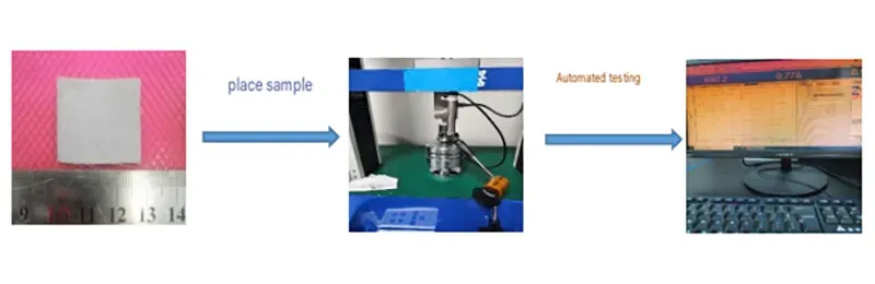
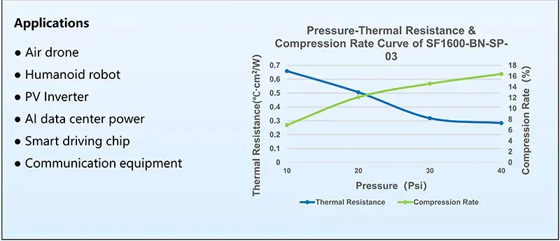
This approach gives the switch pad room to conform without pushing the hardware too hard.
Ensuring Dielectric Breakdown Voltage in Network Switch Chassis
A Thermal Pad for a switch ASIC may sit between electrically active hardware and a grounded heat sink or Chassis, making insulation performance just as important as cooling.
Insulation requirements
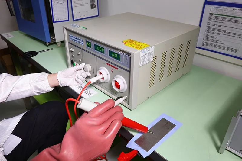
Confirm Dielectric breakdown voltage at the actual pad thickness.
- Voltage withstand should include a suitable design margin.
- High volume resistivity helps limit leakage current.
Review installation conditions.
- Electrical insulation must remain dependable after compression.
- The Insulation material should resist damage from edges and assembly pressure.
System validation
- Test inside the final Network switch, not only on material samples.
- Verify required Electrical safety performance after aging and environmental testing.
| Factor | Key Parameters | Test Standard | Selection Note |
| Heat Transfer | Thermal conductivity, thermal impedance | ASTM D5470 (steady-state) | Evaluate at actual thickness + pressure, not peak W/m·K |
| Mechanical Fit | Shore hardness, compression, set | ASTM D575 / D395 | Confirm compression fills tolerance without over-stressing package |
| Dielectric | Breakdown voltage, volume resistivity | ASTM D149 / IEC 60243, ASTM D257 | Verify at compressed thickness in final assembly |
Sheen Technology can align dielectric and thermal pad properties with chassis spacing, helping avoid shorts while preserving the required cooling path.
Choosing the Right Pad — Silicone vs. Ceramic-Filled vs. Graphite
A Thermal Pad for a switch ASIC has to move heat efficiently while handling package tolerances, mounting pressure, and electrical safety. That can get tricky fast on high-current hardware. Silicone, ceramic-filled silicone, and graphite each solve a different part of the thermal problem, so choosing a Switch ASIC thermal pad means balancing heat flow, mechanical fit, and isolation rather than chasing one headline number.
Cross-Material Comparison
Silicone vs. ceramic-filled silicone vs. graphite sheet:
| Property | Silicone Elastomer | Ceramic-Filled Silicone | Graphite Sheet |
| Heat Transfer Mode | Bulk conduction + gap fill | Higher-filler bulk conduction | In-plane spreading dominant |
| Thermal Conductivity | 1–15 W/m·K (typical) | 3–16 W/m·K (typical) | In-plane 700–1500 / through 75–90 W/m·K |
| Electrical Insulation | Yes (must be verified) | Yes (higher dielectric) | No — conductive, needs edge isolation |
| Gap-Filling / Compliance | Good | Moderate (stiffer) | Poor (flat surfaces only) |
| Typical Use | Tolerance + vibration damping | High power + isolation | Thin flat interface + lateral spreading |
Note: conductivity values are typical ranges. Final selection must use Sheen product datasheet values measured at the specified thickness, pressure, and temperature.
Need thermal conductivity, thermal impedance, shore hardness, dielectric breakdown voltage, and compression ratio data for high-power switch ASIC thermal pads? Download the product datasheets to compare silicone elastomer pads, ceramic powder filler pads, and graphite sheet pads for network switch chassis, data center switches, and ASIC heat sink interfaces.
Silicone Elastomer Pads
Silicone pads are forgiving when ASIC and heatsink surfaces are not perfectly flat. Their silicone matrix provides useful conformability, while controlled compression fills small gaps and cuts interface resistance.

For practical selection:
- Check thermal conductivity against heat flux and pad thickness.
- Match hardness to package pressure limits; softer is not automatically better.
- Verify electrical insulation for the working voltage and assembly geometry.
A Thermal Pad for Switch ASIC made from silicone can also absorb vibration, which is handy in tightly packed network equipment.
Ceramic Powder Filler Pads
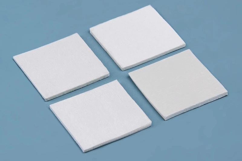
Ceramic-filled silicone pushes heat performance higher without giving up dielectric isolation. The catch is that greater filler loading may make a pad stiffer.
Compare filler chemistry:
- alumina filler offers a common cost-performance balance.
- boron nitride can provide higher thermal performance with electrical insulation.
Check physical details:
- particle size affects packing and mechanical response.
- dielectric strength matters near exposed conductors.
Validate thermal and aging results:
- Compare thermal impedance, not conductivity alone.
- Review compression aging, oil bleed, and long-term reliability.
Graphite Sheet Pads
Graphite is a different beast: it spreads heat extremely well sideways, but conducts electricity.
| Graphite property | Typical value | Design implication |
| thickness | 0.025–0.10 mm | Very thin interface |
| In-plane conductivity | 700–1,500 W/m·K | Strong in-plane heat transfer |
| Sheen Technology Graphene sheet | 75–90 W/m·K | Strong vertical flow |
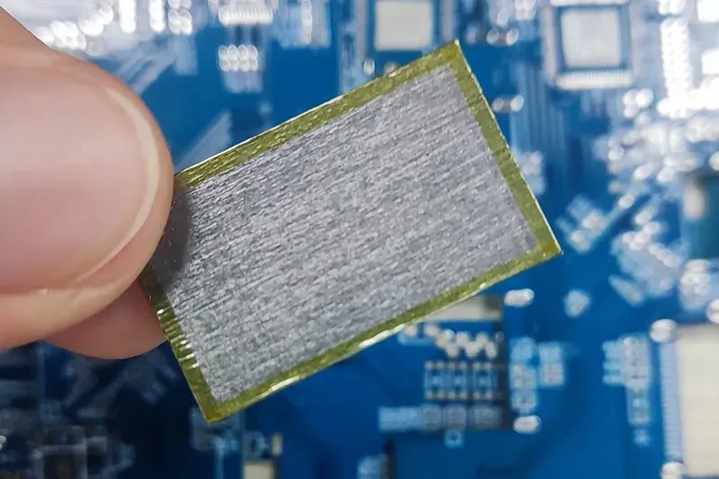
Material choice matters:
- natural graphite offers high spreading performance and flexibility.
- synthetic graphite supports very high anisotropic thermal conductivity in thin designs.
Integration matters too:
- Edge insulation helps prevent electrical contact with circuitry or chassis.
- Low thickness can produce low thermal resistance, but graphite is not a direct dielectric substitute for a switch ASIC pad.
AI networking is moving toward 800G and 1.6T optical modules, along with emerging Co-Packaged Optics (CPO) architectures. As data rates increase, thermal density also becomes a more important design constraint around switch ASICs, SerDes, retimers, voltage regulator modules (VRMs), and optical interfaces. NVIDIA has already incorporated 800G and CPO technologies into AI networking platforms, while Broadcom continues to advance 800G and 1.6T switch architectures. The OSFP specification also addresses “riding heatsinks,” highlighting the importance of the thermal interface between an optical module and its heatsink. In these designs, the TIM is not simply a filler material—it becomes an important part of the overall thermal path and must be selected for thermal performance, compliance, thickness, compression, and long-term reliability.
Data Center Switches: Optimal Pad Selection
Choosing a Thermal Pad for Switch ASIC hardware comes down to more than a conductivity number. Heat, fit, material safety, and storage all affect performance once a switch runs around the clock. A well-matched ASIC thermal pad keeps temperatures under control without creating assembly headaches, and that matters when racks stay busy day and night.
Operating Temperature Range and Thermal Impedance Alignment
A Thermal Pad for Switch ASIC should be evaluated under realistic power and compression conditions.
Thermal performance
- Compare thermal conductivity at the specified pad thickness.
- Calculate total thermal resistance, including interfaces and material thickness.
Operating conditions
- Keep ASIC junction temperature below its rated operating limits during peak traffic.
- Check heat dissipation after repeated hot-cold cycles.
Material behavior
- Verify compressed thickness at real mounting pressure.
- If a phase change material is considered, confirm its transition temperature suits normal switch operation.
That approach gives engineers a much clearer apples-to-apples comparison.
Die-cut Precision for ASIC Chip Package and Heat Sink Interface

Good thermal material still performs poorly when the fit is off. Specify die-cutting dimensions around the actual package, then apply tight tolerance control to length, width, and thickness.
- Measure the required interface area without covering nearby capacitors.
- Set gap thickness from assembled hardware, not nominal drawings alone.
- Confirm suitable contact pressure across the ASIC.
Account for heat-sink surface roughness, which can create tiny insulating air gaps.
A properly sized ASIC thermal pad should compress evenly without excessive squeeze-out.
RoHS Compliance, REACH Regulation, and Outgassing Rate Verification
Material qualification deserves the same attention as thermal performance.
Compliance records
- Verify RoHS limits for regulated hazardous substances.
- Review current REACH declarations and applicable environmental standards.
Reliability evidence
- Check volatile organic compounds and measured mass loss under the specified test method.
- Confirm flame-retardant requirements where applicable.
Supplier documentation
- Retain declarations supporting regulatory compliance.
- Review SDS information as part of material safety controls.
Low-outgassing switch thermal pad materials help limit deposits inside tightly packed chassis.
Shelf Life, Storage Condition, and Packaging Format Considerations
Don’t overlook the stockroom side of the job. A Thermal Pad for a switch ASIC can change before installation when handling controls are poor.
- Record approved storage temperature and humidity control limits.
- Track stated shelf life by lot and manufacturing date.
- Keep the release liner intact until assembly to protect surfaces.
- Select sheet or roll format based on die-cut and production needs.
Use sealed packaging where oxidation prevention is relevant, while maintaining batch traceability from incoming inspection through switch assembly.
Selection Decision Framework
Decision framework for high-power switch ASIC pads:
| Priority Scenario | Preferred Material | Key Validation |
| Flat surfaces, extreme lateral spreading needed | Graphite sheet \ Graphene sheet | Edge isolation, contact pressure, directionality |
| Surface tolerance / uneven gap, vibration | Silicone elastomer | Compression ratio, Shore hardness, rebound |
| High power + high dielectric + gap fill | Ceramic-filled silicone | Dielectric at actual thickness, thermal impedance, aging |
| High power density, space-constrained | BN-filled thin pad | Through-plane conductivity, dielectric, thickness tolerance |
Selecting a thermal pad for a high-power switch ASIC is a multi-parameter engineering decision, not a single-number comparison. Match thermal conductivity and thickness to heat flux, balance hardness and compression for contact reliability, and verify dielectric strength at the actual compressed thickness. Silicone elastomer, ceramic-filled silicone, and graphite each solve a different part of the problem — the right choice depends on surface flatness, electrical isolation requirements, and the direction heat must travel. Sheen Technology provides switch ASIC thermal pads with ASTM/IEC-referenced data, die-cut tolerance control, and application engineering support.
→ Contact Sheen Technology for Switch ASIC Pad Selection Support
Sheen Thermal
Dongguan Sheen Electronic Technology Co., Ltd · Founded in 2008
Manufacturer of thermal interface materials and silicone foam for automotive electronics, energy storage, power electronics, communications and consumer electronics.
Certified
- ISO 9001:2015
- ISO 14001:2015
- IATF 16949:2016
What we supply
- Thermal conductivity Up to 90 W/m·K
- Thickness 0.3–10.0 mm
- Custom & samples Die-cut to drawing, 3–7 days