
 English
 usheenthermal

What Is a Thermal Resistance and Thermal Impedance?
Date:2026-07-01
What Is a Thermal Resistance and Thermal Impedance?
Thermal Resistance and Thermal Impedance decide if your device runs cool or cooks itself, and buyers don’t notice until performance tanks or parts fail early. Heat doesn’t care about budgets or deadlines; it builds up, quietly wrecking margins and reliability.
Understanding the difference turns guesswork into smart sourcing, helping you pick materials that handle real spikes, not steady heat.
Reading Notes on Thermal Resistance and Thermal Impedance
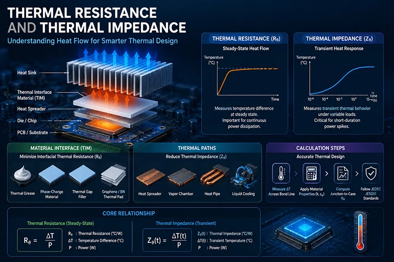
➔ Core Concepts: Distinguish steady-state thermal resistance (Rθ) from transient thermal impedance (Zθ) to predict both long-term and spike heating in power semiconductors and ICs.
➔ Material Interface: Choose TIMs—grease, phase-change, gap fillers—based on conductivity, bond-line thickness, and application to minimize interfacial Rθ.
➔ Thermal Paths: Leverage heat spreaders, vapor chambers, heat pipes, and liquid cooling to lower Zθ and maintain CPU/GPU reliability under dynamic loads.
➔ Calculation Steps: Measure ΔT across bond line, apply conductivity and specific heat data, then compute junction-to-case Rθ per JEDEC JESD51 for accurate thermal design.
Types Of Thermal Resistance And Thermal Impedance
Modern cooling hardware lives or dies by Thermal Resistance and Thermal Impedance control. From EV inverters to gaming GPUs, stable Heat Flow keeps silicon safe, lowers throttling, and stretches operating life without crazy cooling costs.
Junction-to-case thermal resistance in power semiconductors
In a Power Semiconductor, Junction heat must move through the Die and Package before reaching the Case. Low Thermal Resistance means faster Heat Dissipation and lower junction temperature drift.
· MOSFET packages target tighter junction-to-case paths.
· IGBT modules rely on copper baseplates and solder quality.
· Automotive drives monitor thermal rise during rapid load swings.
Lower resistance improves switching stability. Poor package contact raises hotspot risk.
IDC noted in a 2025 thermal management outlook that transient heat density in automotive power electronics keeps climbing faster than package miniaturization can offset.
Comparing thermal resistance vs. thermal impedance
Thermal Resistance and Thermal Impedance are related, though not identical. Steady-State values describe final equilibrium temperature, while Transient response tracks Time-dependent heating.
· Thermal Resistance: fixed-state thermal path.
· Thermal Impedance: dynamic temperature behavior.
Nested analysis used by CPU designers:
Chip load spike
· rapid Temperature increase
· delayed heatsink response
Cooling stabilization
· normalized Heat Flow
· reduced impedance curve
Sheen Technology often evaluates both thermal metrics during server cooling validation because thermal impedance spikes can appear even when steady resistance numbers look fine.
Role of TIMs: thermal grease, phase change materials, and gap fillers
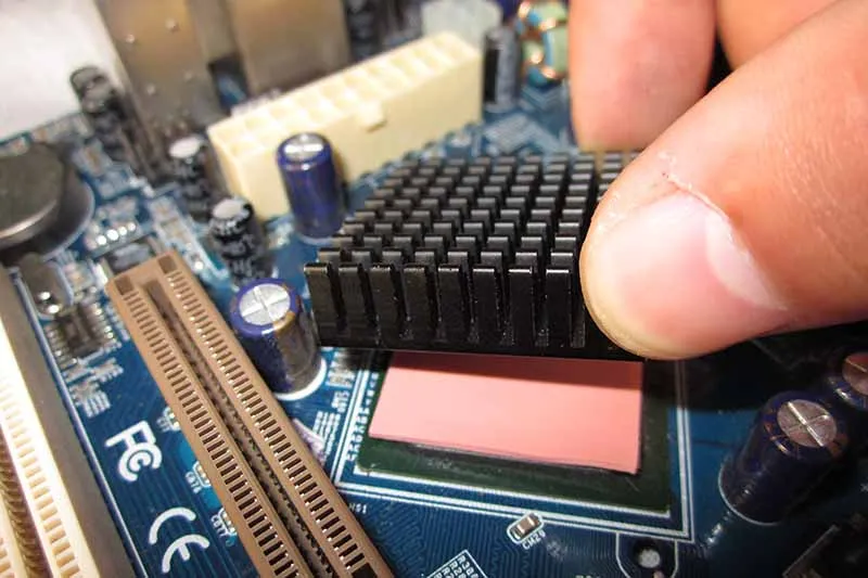
A Thermal Interface Material fills tiny surface gaps where trapped air hurts Heat Transfer. Thermal Grease, Phase Change Material, and Gap Filler products each balance Conductivity, pressure, and long-term Contact stability.
Short practical picks:
· Grease for CPUs
· Gap fillers for EV modules
· Phase materials for compact notebooks
Bad bond-line thickness can quietly wreck Thermal Resistance and Thermal Impedance performance.
Thermal impedance in heat spreader and vapor chamber solutions
A Heat Spreader distributes localized heat before throttling begins. A Vapor Chamber uses liquid evaporation inside a sealed Wick Structure, moving energy between Evaporator and Condenser regions through controlled Phase Change.
Typical optimization flow:
· Reduce hotspot concentration
· Flatten package temperature map
· Lower overall Thermal Impedance
Sheen Technology applies these cooling methods in dense AI hardware where Thermal Resistance and Thermal Impedance directly affect rack power efficiency and sustained GPU boost clocks.
Need verified thermal conductivity, thermal resistance, thermal impedance, and interface material performance data before selecting a cooling solution? Download the product datasheets to compare thermal interface materials—including thermal pads, thermal grease, phase change materials, and gap fillers—for AI servers, power electronics, automotive systems, and high-performance computing.
Why Thermal Impedance Matters In Design
High power electronics live or die by how well engineers manage Thermal Resistance and Thermal Impedance. Break the phrase down—thermal resistance, thermal impedance, heat flow, junction temperature—and it becomes clear: control heat, protect performance, extend life.
Ensuring CPU and GPU reliability under high thermal loads
When CPU and GPU systems run under heavy thermal loads, the battle is fought at the junction level.
Device Layer
1.1 Temperature rise increases leakage current.
1.2 Higher leakage cuts performance stability.
1.3 Poor thermal impedance accelerates overheating.
Package Layer
2.1 Die attach materials define baseline thermal resistance.
2.2 Substrate design influences total Thermal Resistance and Thermal Impedance.
2.3 Interface gaps quietly add unwanted thermal resistance.
System Layer
· Airflow quality
· Heatsink pressure
· Ambient control
Key reliability metrics:
| Power (W) | Junction Temp (°C) | Thermal Resistance (°C/W) | Thermal Impedance (°C/W) | MTBF (hrs) |
| 95 | 88 | 0.52 | 0.60 | 120,000 |
| 125 | 96 | 0.48 | 0.55 | 105,000 |
| 180 | 110 | 0.42 | 0.50 | 82,000 |
| 220 | 124 | 0.38 | 0.46 | 60,000 |
| 300 | 142 | 0.35 | 0.41 | 41,000 |
Lower Thermal Resistance and Thermal Impedance equals longer reliability life. It’s that simple.
Sheen Technology helps validate thermal resistance and transient thermal impedance early, so chips don’t throttle when it counts.
Optimizing heat sink, heat pipe, and liquid cooling performance
Cooling hardware only works as well as the measured thermal transfer path.
A quick breakdown:
· Heat sink base flatness reduces contact thermal resistance.
· Heat pipe wick structure impacts dynamic thermal impedance.
· Liquid cooling cold plates depend on flow uniformity.
Optimization flow:
· Measure baseline Thermal Resistance and Thermal Impedance.
· Adjust contact pressure and interface materials.
· Re-test transient thermal impedance under pulse load.
· Compare steady-state thermal resistance curves.
If the numbers don’t move, the design doesn’t improve.
In 2025, Gartner noted:
“Thermal density in AI accelerators continues to outpace conventional cooling assumptions, demanding tighter thermal characterization and validation.”
That means thermal design is no longer guesswork. It’s measured. It’s modeled. It’s verified.
With advanced thermal impedance testing systems from Sheen Technology, engineers tune cooling solutions with real data, not hope.
Meeting JEDEC JESD51 standards and reliability testing requirements
Compliance isn’t paperwork—it’s proof.
Under JEDEC JESD51:
Measurement Conditions
1.1 Controlled airflow
1.2 Defined board layout
1.3 Calibrated sensors
Thermal Characterization
· Steady-state thermal resistance
· Transient thermal impedance
· Junction-to-case metrics
Reliability Testing
3.1 Thermal cycling
3.2 Power cycling
3.3 Long-duration stress
Accurate Thermal Resistance and Thermal Impedance data ensures alignment with thermal standards, test methods, and industry compliance rules.
Engineers working with Sheen Technology gain traceable data that supports qualification in automotive, telecom, and high-performance computing markets.
When thermal resistance is controlled and thermal impedance is understood, hardware lasts longer—and passes testing the first time.
Want to see how thermal interface materials reduce thermal resistance and improve thermal impedance in real products? Browse these related application pages to explore practical thermal management solutions across demanding electronic systems.
3 Steps To Calculate Thermal Resistance
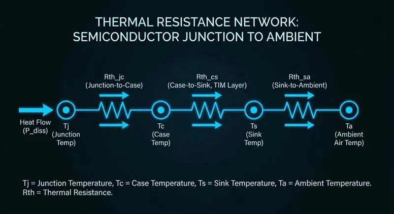
Getting accurate values for Thermal Resistance and Thermal Impedance is not just lab stuff anymore. Engineers working with power electronics, compact IC layouts, and dense cooling paths rely on precise thermal resistance data every day. Sheen Technology supports faster thermal validation by helping teams connect temperature, heat transfer, and semiconductor cooling behavior without turning the process into a headache.
Step 1: Measure temperature drop across the bond line thickness
For reliable Thermal Resistance and Thermal Impedance analysis, the temperature drop across the bond line must stay consistent during testing.
· Check sensor placement near the thermal interface
· Keep thickness uniform across the contact area
· Record stable measurement values under fixed power load
Apply the TIM evenly.
· Stabilize operating temperature.
· Measure both surface temperatures.
· Calculate the delta across the bond line.
“Thermal management accuracy is becoming a key differentiator in power semiconductor reliability,” noted a 2025 Yole Group packaging report discussing advanced cooling validation.
Small gaps, trapped air, or uneven paste spread can distort Thermal Resistance and Thermal Impedance calculations pretty fast.
Step 2: Calculate using thermal conductivity and specific heat capacity
Thermal Resistance and Thermal Impedance depend heavily on material properties.
Core calculation inputs:
· thermal conductivity:higher conductivity lowers resistance.
· geometry:thinner layers improve heat transfer.
· contact area:larger surfaces reduce hot spots.
For transient conditions, specific heat capacity matters because stored heat changes response time. A MOSFET that survives steady load may still spike during pulse operation. That is where thermal impedance becomes useful instead of relying only on static thermal resistance values.
Sheen Technology often recommends comparing steady-state and transient data side by side for tighter calculation accuracy.
Step 3: Determine junction-to-case resistance for MOSFETs and ICs
When analyzing MOSFETs, ICs, or power packages, junction-to-case resistance gives a direct look at internal heat dissipation performance.
• Pull values from validated datasheets
• Use JEDEC test methods when possible
• Compare package types under identical airflow
Nested checks help avoid bad assumptions:
Semiconductor package review
· TO-220
· QFN
· BGA
Internal thermal path
· die attach quality
· case material
· interface pressure
Accurate Thermal Resistance and Thermal Impedance modeling protects long-term semiconductor reliability and keeps package temperatures under control during high-current operation.
【Request a Custom Quote】 Selecting the right thermal interface material depends on your heat load, interface design, operating temperature, mechanical constraints, and reliability requirements. Share your application details with our engineering team, and we'll help recommend the most suitable thermal management solution to reduce thermal resistance, optimize thermal impedance, and improve long-term system performance.
Sheen Thermal
Dongguan Sheen Electronic Technology Co., Ltd · Founded in 2008
Manufacturer of thermal interface materials and silicone foam for automotive electronics, energy storage, power electronics, communications and consumer electronics.
Certified
- ISO 9001:2015
- ISO 14001:2015
- IATF 16949:2016
What we supply
- Thermal conductivity Up to 90 W/m·K
- Thickness 0.3–10.0 mm
- Custom & samples Die-cut to drawing, 3–7 days