
 English
 usheenthermal

How to Choose the Best Thermal Interface Material for Solar Inverter
Date:2026-08-12
Choosing a thermal interface material for solar inverter by conductivity alone is a gamble. Bond lines, cycling, and insulation can rewrite the result.
For volume production, process fit matters too. Dispensing, storage, rework, and price can turn a datasheet darling into a factory headache.
Sheen Technology engineers recommend matching TIM specifications to inverter design and manufacturing conditions.
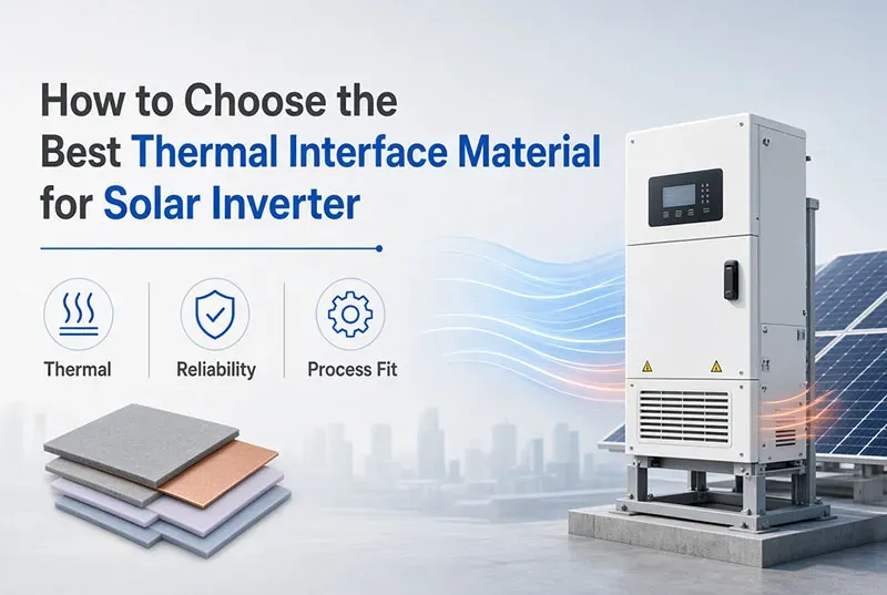
Quick Answers: Thermal Interface Material for Solar Inverter Selection
➔ Conductivity vs. Resistance: Balance bulk thermal conductivity with interface resistance and bond-line thickness for optimal heat flow.
➔ Thermal Cycling Stability: Choose materials that withstand repeated temperature swings without cracking, pumping out, or hardening.
➔ Electrical Insulation: Verify dielectric strength, breakdown voltage and volume resistivity to prevent leakage in high-voltage inverter stacks.
➔ Material Handling: Match viscosity, thixotropy, curing profile and dispensing method to your automated or manual assembly process.
➔ Environmental Durability: Ensure long-term moisture, UV, vibration and thermal shock resistance for outdoor solar inverter applications.
7 Critical Factors in Picking Thermal Interface Material
Choosing the right thermal interface material for solar inverter hardware is about more than chasing the highest conductivity number. Real inverter designs balance heat flow, electrical safety, application control, and outdoor durability. From semiconductor packages to a heat sink, Sheen Technology helps engineers match solar inverter thermal materials with production needs and long service conditions without making things overly complicated.
Thermal Conductivity vs. Heat Transfer Coefficient Balance
High thermal conductivity looks great on paper, but interface resistance and thermal resistance can still bottleneck heat dissipation. For a thermal interface material for solar inverter design, check heat flux, bond thickness, and real assembly thermal impedance alongside the heat transfer coefficient.
Operating Temperature Range and Thermal Cycling Stability
A wide temperature range is only part of the story. Repeated thermal cycling creates stress through uneven thermal expansion, so verify thermal stability across the specified operating temperature and watch for cracking, pump-out, or material degradation.
Electrical Insulation: Dielectric Strength and Volume Resistivity
For electrically sensitive assemblies:
- Confirm dielectric strength and rated breakdown voltage.
- Check volume resistivity under expected conditions.
- Keep leakage current and unwanted electrical conductivity low.
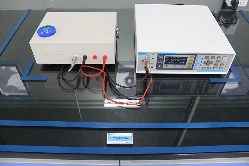
Good electrical insulation cannot be traded away just to gain thermal performance.
Viscosity, Thixotropy, and Optimal Bond Line Thickness
Viscosity controls material flow during dispensing, while thixotropy helps material stay put after application. Sheen Technology thermal interface products can be evaluated for predictable gap filling, controlled bond line thickness, suitable rheology, and lower contact resistance.
Silicone-Based vs. Non-Silicone Polymer Matrix Compositions
 |  |
- Silicone formulations often favor flexibility and broad temperature performance.
- Non-silicone options address silicone-contamination concerns in sensitive manufacturing.
Compare each polymer matrix, its organic polymers, inorganic fillers, and overall material composition before picking between material types.
Moisture Resistance, UV Resistance, and Long-Term Stability
Outdoor reliability calls for moisture resistance under humidity plus suitable UV resistance where exposure can occur. A thermal interface material for solar inverter use should also limit oxidation, environmental degradation, and material aging, preserving long-term stability and reliability year after year.
Automated Dispensing and Material Handling Considerations
Production can make or break a good material choice. Match automated dispensing equipment to viscosity and the intended application method, then validate:
- Processability and workability during production
- Storage conditions and usable pot life
- Curing behavior and line speed
Sheen Technology can support material selection around practical material handling and production efficiency, not just datasheet performance.
Layered Breakdown: Thermal Interface Material Categories
Choosing a thermal interface material for solar inverter hardware comes down to heat flow, fit, electrical safety, and assembly needs. From thermal paste to pads and liquid metal, each interface option handles inverter heat differently, so the right match really matters.
Thermal Paste: High-Conductivity Ceramic Fillers
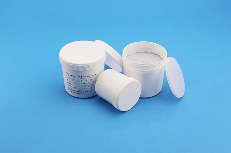
A thermal paste uses a fluid grease carrying a ceramic filler, often boron nitride or alumina. High conductivity and strong surface wetting create a thin interface with low resistance. For a thermal interface material for solar inverter power modules, that’s a handy combo where surfaces already fit closely.
Thermal Pad: Pre-Formed Polymer Matrix Solutions
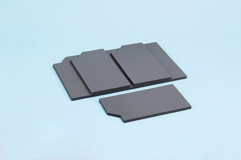
A thermal pad arrives as a pre-formed sheet, keeping installation neat and thickness predictable.
Its polymer matrix or elastomer compresses between inverter parts.
- The interface can also provide electrical isolation.
- Controlled thickness makes assembly less fiddly.
Sheen Technology can help match pad properties to solar inverter thermal demands.
Gap Filler Material: Compressibility for Uneven Surfaces
When tolerances stack up, a gap filler handles spaces that paste cannot comfortably bridge.
- The soft, compressible material contacts an uneven surface.
- Air pockets shrink.
- Thermal interface contact improves.
Lower mechanical loading helps protect sensitive power components. That makes gap filler useful across varied solar inverter assemblies.
Phase Change Material: Optimal Cure Time Performance
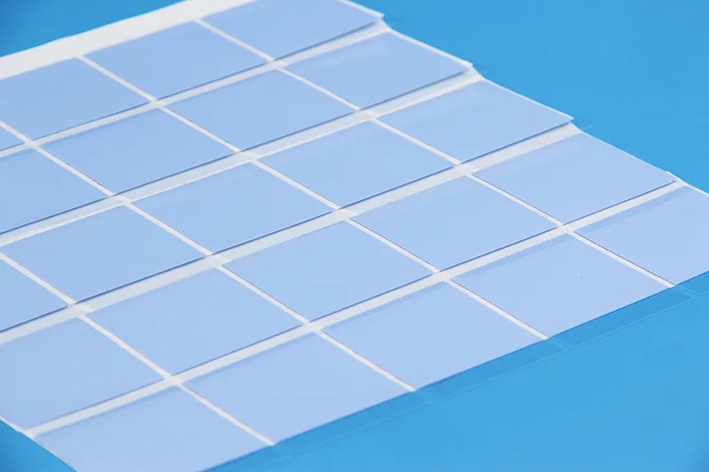
A phase change material stays easy to handle during assembly, then softens around its designed transition temperature.
- Better wetting lowers thermal interface resistance.
- Unlike many adhesives, conventional cure time is not required.
- Stable application supports repeatable performance during production.
For thermal management, it’s a clean, practical middle ground.
Liquid Metal TIM: Metallic Fillers with Superior Conductivity
Liquid metal provides superior thermal conductivity through a metallic medium rather than a conventional filler system.
Check electrical isolation carefully.
- Leakage can short nearby circuitry.
- Some metals can react with aluminum.
Sheen Technology TIM Characteristic Parameters:
| TIM Type | Conductivity (W/m·K) | BLT (μm) | Dielectric (kV/mm) | Rework | Best Inverter Application |
| Thermal Paste | 1–5 | 10–50 | N/A (varies) | Solvent clean | IGBT modules; close-tolerance surfaces |
| Thermal Pad | 1–15 | 100–500 | > 6 | Peel + replace | MOSFET arrays; electrical isolation needed |
| Phase-Change | 3–8 | 25–100 | N/A (flowable) | Heat + clean | IGBT die interface; low-resistance target |
| Liquid Metal | 10–50 | 10–50 | Conductive | Solvent + passivation | Highest heat flux; isolation provided externally |
As a thermal interface material for solar inverter designs, it can move heat extremely well, but compatibility is a must. Need thermal conductivity, dielectric strength, bond line thickness, thermal cycling stability, and RoHS/REACH compliance data for thermal interface materials? Download the product datasheets to compare thermal paste, thermal pads, gap fillers, phase change materials, and liquid metal TIMs for solar inverters, IGBT modules, and renewable energy systems.
Affordable vs. Premium TIM—Which Is Better?
Price alone rarely tells the full story when choosing a thermal interface material for solar inverter hardware. Heat output, assembly pressure, electrical insulation, expected service life, and production methods all matter. Sheen Technology helps inverter designers compare practical thermal material choices against application needs, so an attractive unit price does not turn into a costly thermal headache later.
Affordable TIM
A Cost-effective thermal interface material for solar inverter designs can work well where heat density stays moderate and mechanical tolerances are predictable. The key is matching material capability to the inverter instead of simply grabbing the cheapest option.
- Start with thermal needs. Standard thermal conductivity may provide enough heat transfer for many inverter power components, especially when the interface area is generous.
- Check assembly conditions. A Grease can create a thin contact layer, while a Pad offers tidy placement and straightforward handling. Silicone-based products are also common where insulation and flexibility count.
- Consider production. Ease of use can cut assembly hassle and support repeatable application. Basic performance is perfectly practical when qualification testing confirms temperature resistance, aging behavior, and electrical requirements.
Sheen Technology can support material selection with thermal, insulation, and manufacturing considerations in mind.
Premium TIM
Premium thermal material becomes attractive as solar inverter power density rises, particularly around tightly packed IGBT or other power semiconductor assemblies.
Higher thermal capability
- High thermal conductivity helps move heat toward the heatsink with less interface resistance.
- Advanced materials can support thinner bond lines or demanding operating temperatures.
Specialized interface choices
- Phase change materials can soften at working temperatures to improve surface contact.
- Boron nitride thermal pads offer high thermal conductivity and excellent insulation.
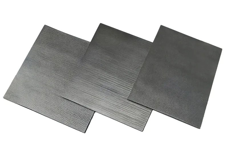
- Graphene thermal pads possess extremely high thermal conductivity; Sheen Technology's graphene thermal pads boast a vertical thermal conductivity of up to 90W, providing efficient thermal conduction for heat dissipation needs.
Lifetime priorities
- Durability and Long-term stability matter under repeated heating and cooling.
- High reliability can justify the added cost when downtime carries a bigger price tag.
For a high-power thermal interface material for a solar inverter platform, Sheen Technology can help balance inverter cooling performance, reliability, manufacturability, and total cost rather than chasing conductivity numbers alone.
→ Request Solar Inverter TIM Cost-Benefit Analysis
5 Steps to Test Your Installed TIM
Testing a thermal interface material for solar inverter hardware means checking heat transfer, fit, electrical safety, and aging under practical loads. A few focused checks can catch small installation issues before they turn into costly inverter headaches.
Measure Thermal Resistance Across the Interface
Record the temperature gradient while applying a known heat flux through the TIM layer. From that measurement, calculate thermal resistance across the interface, taking contact resistance and stated thermal conductivity into account.
Keep inverter loading representative of normal service.
- Stable readings make thermal interface comparisons far more useful.
- A thermal interface material for solar inverter should meet the thermal design target without surprise hot spots.
Inspect Bond Line Thickness and Compressibility
Check bond line thickness at several locations rather than trusting one spot. Proper compressibility supports gap filling, while controlled mounting pressure promotes void reduction and wider contact area.
Look closely at material deformation after assembly. Good TIM application avoids squeezed-out material and trapped air—simple stuff, but easy to miss.
Evaluate Heat Dissipation on IGBT Modules
Run the IGBT modules at realistic conversion loads and track junction temperature or case temperature. Effective heat dissipation should move energy toward the heat sink without excessive temperature rise.
Compare results across operating conditions.
- Check cooling efficiency as load increases.
- Confirm overall thermal performance supports the intended solar inverter rating.
Sheen Technology can support thermal interface material selection when installed behavior needs to match demanding power electronics conditions.
Verify Dielectric Strength and Non-Conductive Integrity
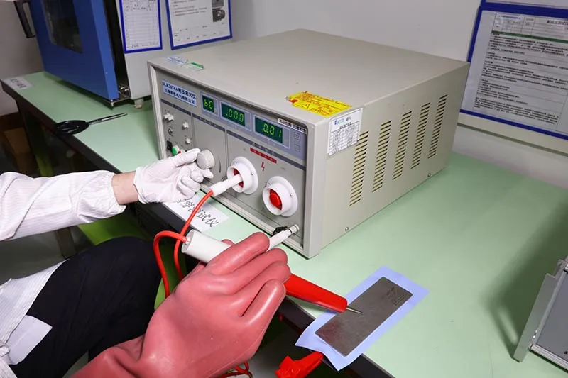
For electrically isolated assemblies, verify dielectric strength, breakdown voltage, and insulation resistance. The non-conductive material properties must preserve electrical insulation around high-voltage devices.
A thermal interface material for solar inverter also needs low leakage current and stable insulation integrity. That keeps electrical safety from becoming an afterthought.
Assess Thermal Cycling Stability Over Time
Repeat thermal cycling across expected temperature fluctuations, then inspect for pump-out, cracking, or separation.
Track stability and thermal results between cycles.
- Watch for degradation caused by aging.
- Inspect material fatigue around compressed edges.
Compare later readings with the baseline.
- Consistent long-term performance indicates better reliability for the installed solar inverter TIM.
Can You Over-Apply Thermal Compound?
Yes. Applying too much thermal interface material for solar inverter assemblies can hurt cooling rather than help it. A correctly controlled thermal interface fills microscopic surface gaps without becoming a thick barrier. For inverter service teams, Sheen Technology recommends matching compound quantity, mounting force, and supplier specifications instead of assuming that more paste means better cooling.
How Excess Viscosity Impacts Heat Transfer Efficiency
A thicker interface changes the thermal path.
- High viscosity can prevent the compound from spreading into a thin, even interface layer.
- Excessive film thickness increases thermal resistance, even when the material itself has good thermal conductivity.
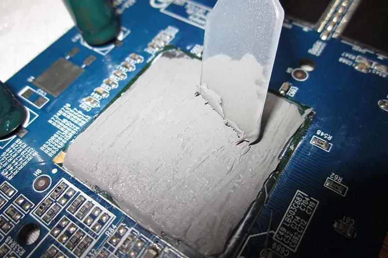
Heat then travels through more compound before reaching the cooler. Heat transfer and overall thermal performance can drop under inverter loads.
A well-applied thermal interface material for solar inverter hardware is basically about filling tiny gaps, not building another layer. Keeping the solar inverter interface thin helps maintain predictable heat dissipation.
Signs of Compound Squeeze-Out on Heat Sinks
During visual inspection, check the perimeter where the power module meets the heat sink. A small controlled trace may be normal, but heavy squeeze-out deserves attention.
- Watch for thermal compound collecting near terminals or nearby parts.
- Check the mating area for uneven coverage or air gaps.
- Look for dried, separated, or cracked material that could indicate material degradation.
Conductive compounds raise the stakes because escaped material may contribute to component damage. Sheen Technology advises verifying the specified thermal interface material and application quantity before treating visible overflow as harmless.
Best Practices to Remove and Reapply Incorrect Layers
Remove the module carefully.
- Wipe away bulk thermal paste without scratching either mating face.
- Complete residue removal using a supplier-approved cleaner; suitable isopropyl alcohol is commonly used where component guidance permits it.
Prepare the interface.
- Finish surface cleaning and inspect for contamination or damage.
- Do not stack paste over a thermal pad unless the assembly specification explicitly calls for it.
Complete reapplication.
- Use the specified dose and proper spreading method.
- Apply the specified contact pressure and fastening sequence.
Solar inverter TIM selection is fundamentally a systems-engineering exercise: the material must perform thermally and electrically within a specific mechanical assembly, survive 15–25 years of outdoor environmental exposure, and integrate into a cost-effective production process. The 7-factor framework, 5-category comparison, and 5-step validation methodology presented in this guide provide a structured approach to TIM specification. Sheen Technology supports solar inverter manufacturers with application engineering, ASTM/IEC-referenced test data, and production-integration guidance throughout the product development and manufacturing lifecycle.
→ Contact Sheen Technology for Solar Inverter TIM Engineering Support
Sheen Thermal
Dongguan Sheen Electronic Technology Co., Ltd · Founded in 2008
Manufacturer of thermal interface materials and silicone foam for automotive electronics, energy storage, power electronics, communications and consumer electronics.
Certified
- ISO 9001:2015
- ISO 14001:2015
- IATF 16949:2016
What we supply
- Thermal conductivity Up to 90 W/m·K
- Thickness 0.3–10.0 mm
- Custom & samples Die-cut to drawing, 3–7 days