
 English
 usheenthermal

How to Select the Best Thermal Interface Material for Power Inverter:IGBT, SiC & GaN Engineering Guide
Date:2026-08-13
Choosing a thermal interface material for power inverter is not a highest-conductivity-wins contest. IGBT, SiC, and GaN devices push serious heat toward the heatsink, and microscopic gaps can turn that path into a thermal traffic jam.
Performance hinges on thermal impedance, bond line thickness, electrical isolation, and power cycling stability. For volume production, automated dispensing, consistency, shelf life, and reworkability matter too.
Melodic Key Points: Thermal Interface Material for Power Inverter
- Optimize Thermal Impedance: Balance high conductivity with minimal bond‐line thickness to ensure efficient junction‐to‐heatsink heat flow.
- Ensure Electrical Isolation: Select materials with sufficient dielectric strength—especially around IGBTs, MOSFETs, and SiC/GaN semiconductors.
- Prioritize Long-Term Stability: Choose TIMs resistant to pump-out, dry-out, and creep under repeated power cycling.
- Enable Automated Production: Verify viscosity and form factor (dispense, film, pad) for consistent automated dispensing, stable shelf life, and easy rework.
Why Is TIM Crucial for Power Inverter Cooling?
A thermal interface material for power inverter cooling closes tiny air gaps where hot components meet a heatsink. That small interface helps heat escape faster, keeping demanding inverter hardware running safely.
Heat Dissipation Challenges in IGBT Modules
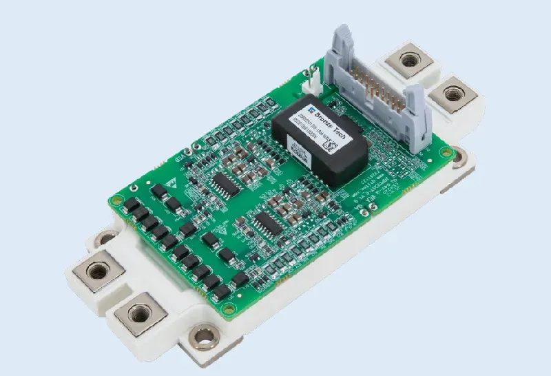
An IGBT inside a power module can produce high heat flux because switching losses build up quickly. Air pockets at the heatsink contact are bad news: air conducts heat poorly, raising thermal resistance and junction temperature.
At the hot interface:
- A thermal interface material for power inverter hardware fills microscopic surface gaps.
- Better contact lowers the operating temperature, giving heat a cleaner route toward the cooler.
How Thermal Conductivity and Impedance Impact Cooling
Thermal conductivity describes how readily heat moves through TIM, but conductivity alone does not tell the whole story.
| TIM example | Thickness(mm) | Conductivity (W/m·K) | Resistance (cm²·K/W) |
| Thermal Grease | - | 1.0-5.0 | 0.09-0.25 |
| Thermal Gel | - | 1.0-12.0 | 0.29-0.83 |
| Thermal Pad | 0.3-10.0 | 1.0-15.0 | 0.64-5.80 |
| Boron Nitride Thermal Pad(SF1600) | 0.3 | 16.0 | ≤0.3 |
| High Performance Graphene Pad | 0.3 | 75-95 | ≤0.10 |
Note: The parameters above are based on actual test data for Sheen products; actual values may vary depending on the test environment, sample thickness, and testing conditions.
Need thermal conductivity, thermal impedance, bond line thickness, dielectric strength, and long-term pump-out resistance data for power inverter TIMs? Download the product datasheets to compare silicone-based TIMs, thermal grease, gap fillers, and phase change materials for IGBT modules, SiC/GaN power stages, and industrial inverter cooling.
Cooling performance depends on:
- Bond line thickness and thermal conductivity, which shape thermal impedance.
- Contact resistance at each surface.
- The total interface layer, where lower resistance improves heat transfer and cooling efficiency.
Values illustrate ideal layer resistance (thickness/conductivity); real assemblies also include contact effects.
Failure Modes from Inadequate Interface Materials
Repeated thermal cycling makes TIM selection especially important.
Mechanical movement may cause:
- pump-out effect, pushing grease away from hot areas;
- delamination or void formation, which block heat flow.
Long service can bring:
- material degradation and cracking;
- rising resistance, overheating, and eventually device failure.
A suitable power inverter thermal interface material must therefore stay stable under heat, pressure, and repeated power cycling—not just post a good conductivity number on paper.
4 Key Factors in TIM Selection
Choosing the right thermal interface material for power inverter designs comes down to more than picking the biggest conductivity number. Heat paths, mechanical fit, electrical safety, and production needs all matter. Sheen Technology helps match power inverter applications with practical thermal materials that support dependable cooling without making assembly a headache.
Thermal Conductivity & Thermal Impedance
For a thermal interface material for power inverter assembly, compare thermal conductivity in W/mK with real thermal impedance.
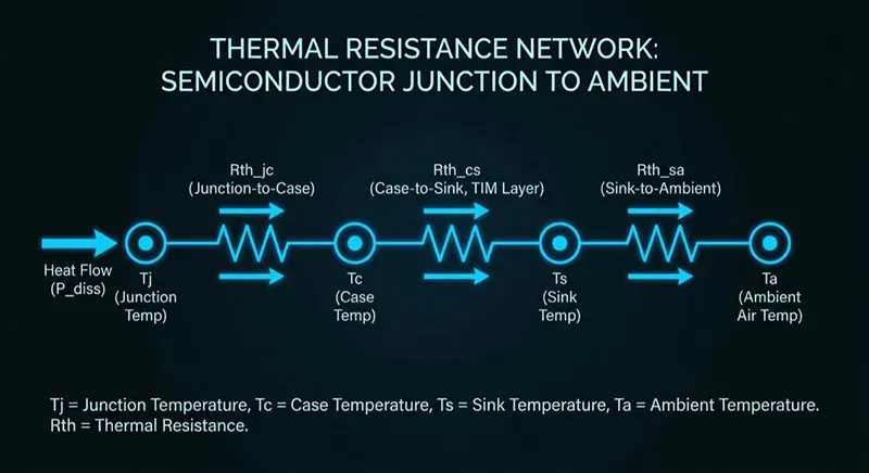
Check the heat path.
- Lower thermal resistance supports better heat transfer.
- Control interface resistance to improve heat dissipation.
A highly conductive paste can still run hot when applied too thickly.
Bond Line Thickness and Compressibility
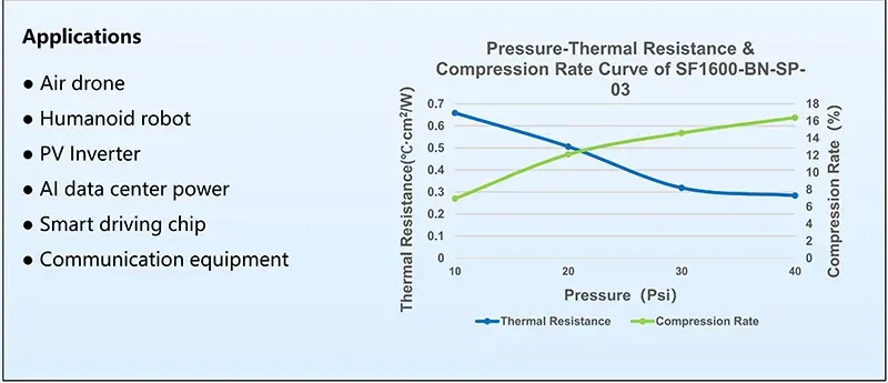
Keep bond line thickness as thin as the design safely allows; extra material can raise contact resistance. A thermal interface material for power inverter hardware also needs enough compressibility for reliable gap filling.
- Match pressure to component limits.
- Allow for surface roughness, material deformation, and changing interface contact.
| Item | SF1600-BN-03 (0.3mm) | Test Standard |
| Available sample thickness | 0.2~5.0 (mm) | ASTM D374 |
| Density (g/cm³) | 1.6±0.2 | ASTM D792 |
| Thermal Resistance (℃*cm²/W) | ≤0.30 (@40Psi) | ASTM D5470 |
| Thermal Conductivity (W/m·K) | 16 | ASTM D5470 |
| Compression Rate (%) | ≥15% (@40Psi) | / |
| Rebound Rate (%) | ≥90 | stand for 30 minutes |
Operating Temperature Range & Dielectric Strength
A thermal interface material for power inverter use must survive the expected operating temperature and full temperature range.
For electrical safety:
- Verify dielectric strength and breakdown voltage.
- Confirm suitable electrical insulation and electrical properties.
For long service life:
- Check performance after thermal cycling.
- Consider inverter-level reliability around IGBTs and MOSFETs.
Sheen Technology can support material selection where cooling and isolation must work together.
Viscosity for Automated Dispensing
For a dispensable thermal interface material for power inverter production:
- Viscosity controls material flow and coverage.
- Rheology and thixotropy affect shape retention after dispensing.
- Automated dispensing requires suitable dispensing speed.
- The application method should fit the wider manufacturing process.
In short, grease or gap filler must run cleanly through production equipment, not just look good on a datasheet.
Performance Criteria for Interface Materials
Choosing a thermal interface material for power inverter hardware comes down to more than a high conductivity figure on a datasheet. Real performance depends on pressure, aging, device temperature, and package design. For day-to-day engineering, Sheen Technology solutions should be assessed against these practical demands before a power inverter design moves toward production.
Thermal Resistance for Efficient Heat Dissipation
A thermal interface material for power inverter assemblies must move device heat across microscopic surface gaps without creating a bottleneck.
Thermal path
- Check thermal conductivity together with bond line thickness; thinner is often better when surface contact stays sound.
- Measure interface resistance under realistic mounting pressure.
Operating conditions
- Compare thermal impedance at expected heat flux.
- Track the temperature gradient through ceramic, copper, or aluminum parts to verify effective heat transfer and heat dissipation.
Long-Term Stability and Pump-Out Resistance
Heat is only half the story. A thermal interface material for power inverter use also faces years of expansion and contraction.
- Test repeated thermal cycling for pump-out, void formation, and separation.
- Check aging for material degradation, including grease dry-out or unwanted phase change.
- Confirm material stability after cycling, not just when new.
Good coverage over time supports long-term reliability.
Power Cycling Reliability Under Load
Repeated switching makes a power inverter interface work pretty hard.
Under realistic load conditions
- Use power cycling to reproduce operating temperature swings.
- Monitor resulting thermal stress and mechanical stress.
After extended testing
- Inspect for fatigue and delamination.
- Watch crack propagation and changes in thermal performance.
A suitable thermal interface material for power inverter designs maintains reliability as loads repeat.
Compatibility with SiC, GaN, and Aluminum Nitride
SiC devices operate at junction temperatures up to 175°C (vs. 150°C for silicon IGBTs) and GaN devices at up to 200°C. TIMs for SiC/GaN applications must maintain thermal and mechanical stability at these elevated temperatures — a requirement that eliminates many standard silicone greases and phase-change materials with lower activation or degradation temperatures.'
Package fit
- Verify material compatibility with aluminum nitride and nearby substrate materials.
- Check adhesion across operating temperatures.
Interface chemistry
- Screen for harmful chemical interaction.
- Consider surface energy, since it affects wetting and contact quality.
A compatible thermal interface compound helps preserve efficient cooling without trading away package life.
Silicone-Based TIMs vs. Thermal Grease: Application-Based Selection
Picking a thermal interface material for power inverter hardware comes down to the mechanical gap, heat path, service conditions, and assembly method. Silicone materials handle uneven spaces nicely, while grease favors close-fitting surfaces. For inverter cooling, the right choice keeps thermal resistance down without creating headaches during production or maintenance.
Silicone-based TIM

A silicone thermal interface material for power inverter assemblies is often a practical fit when components sit at different heights. Its soft structure can fill those spaces while keeping electrical parts separated.
Material behavior
- A silicone polymer can form a flexible elastomer that tolerates repeated heating and cooling.
- Strong conformability helps the TIM contact uneven power inverter surfaces rather than leaving insulating air pockets.
Design considerations
- A gap filler offers useful electrical insulation, but compression pressure must stay within component limits.
- Check thermal conductivity, curing needs, outgassing, and high temperature ratings before locking in the design.
- Long-term durability matters because power cycling can slowly change material thickness.
For a thermal interface material for power inverter design that needs larger-gap coverage, silicone is often the easier route.
Thermal grease
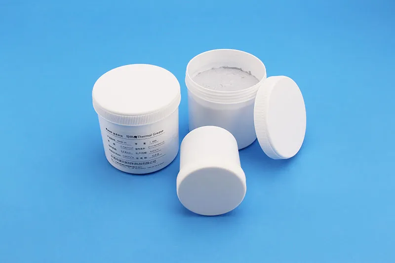
Thermal grease takes a different approach: the paste spreads across closely matched surfaces and produces a thin bond line. That can deliver high performance where interface resistance needs to be very low.
During selection:
- Compare thermal resistance at the real mounting pressure, not just headline conductivity.
- Match viscosity to dispensing equipment so every power module receives a consistent layer.
During qualification:
- Test pump-out under inverter power cycling.
- Check shelf life and storage limits for the non-curing compound.
- Consider reworkability when modules may need servicing.
Comparison table:
| Property | Silicone-Based TIM (Gap Filler / Pad) | Thermal Grease | Engineering Guidance |
| BLT (typical) | 100–500 μm | 10–80 μm | Grease: lower resistance Silicone: larger gaps |
| Dielectric Strength | >10 kV/mm | N/A (varies by filler conductivity) | Silicone: isolation Grease: verify separately |
| Pump-Out Resistance | Excellent | Poor–Moderate | Silicone: cycling stability Grease: reapplication risk |
| Dispensing | Pre-formed or single-part gap filler | Automated dispense (volume control critical) | Silicone: pick-and-place Grease: dispense + inspect |
| Best Application | Uneven gaps, MOSFET arrays, isolation needed | IGBT die, flat clamped surfaces, thin BLT target | Selection = gap + pressure + isolation |
Power inverter TIM selection is fundamentally an impedance-management exercise: the material must create a thin, stable, electrically safe thermal bridge between high-heat-flux semiconductor devices and the heatsink, while surviving years of power cycling without pump-out or degradation. For IGBT, SiC, and GaN power modules, this means evaluating TIMs at the system level — thermal impedance at target BLT, dielectric strength at operating voltage, power cycling stability, and production-line dispensing compatibility. Sheen Technology supports this engineering process with ASTM/IEC-referenced test data, application-specific TIM recommendations, and production-integration guidance.
→ Contact Sheen Technology for Power Inverter TIM Engineering Support
Sheen Thermal
Dongguan Sheen Electronic Technology Co., Ltd · Founded in 2008
Manufacturer of thermal interface materials and silicone foam for automotive electronics, energy storage, power electronics, communications and consumer electronics.
Certified
- ISO 9001:2015
- ISO 14001:2015
- IATF 16949:2016
What we supply
- Thermal conductivity Up to 90 W/m·K
- Thickness 0.3–10.0 mm
- Custom & samples Die-cut to drawing, 3–7 days