
 English
 usheenthermal

Picking a Thermal Gel for AI Servers and Switches? Look Past the Conductivity Number
Date:2026-10-23
AI server power stages, switch line cards, datacenter gear — they all share the same headache. Several devices of different heights sharing one heatsink, tight tolerances, continuous duty, temperature swings, and the occasional repair teardown. The thermal material in the middle has to survive all of it.
Thermal gels earn their spot for three reasons: they conform, they fill, and they dispense. Soft contact on sensitive components. Flexible gap filling. Automated, position-by-position metering that skips the whole die-cut-and-place routine.
But those advantages only count if they hold up in your structure, long term. That’s the real selection criterion.
Sheen’s range: one-part gels from 2 to 12 W/m·K, two-part gels from 2 to 8 W/m·K. Our standing advice — define the interface and the process first, pick the conductivity grade second. If you’re comparing against an incumbent, start sample testing with three quantifiable things: thermal performance, dispensing consistency, and interface retention.
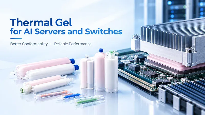
Start with The Real Gaps on Server PSUs and Switch Boards
Take the classic case: multiple devices, one heatsink, different heights — which means different bondline thicknesses at every position. The gel conforms to surface irregularities, squeezes out residual air, and hugs pressure-sensitive devices at low clamp load. Dispensing meters material per position, so no pad cutting, no pad alignment.
Now the catch. A thicker gap means more bulk resistance. Worked example: a uniform 1.5 mm gel layer, simple 1-D steady conduction, contact resistance ignored —
- 6 W/m·K → bulk resistance ≈ 2.5 °C·cm²/W
- 12 W/m·K → bulk resistance ≈ 1.25 °C·cm²/W

Figure 1. Simplified calculation — contact and spreading resistance not included.
Higher conductivity helps. It does not delete thickness. Before asking Sheen for samples, send us your minimum, nominal, and maximum gaps plus your allowable load. And resist the classic trap: cranking screw torque to squeeze the layer thinner just shifts the stress into your package or solder joints. The gel gets thinner; the bill for that arrives later.
From 6 to 12 W/m·K: Read the Data Before You Upgrade
Sheen’s core take on high-conductivity gels: the higher the number, the harder you should look at the trade-off between filler loading, flow behavior, and shape retention.
- More filler can make dispensing noticeably harder.
- If processability comes back mainly via lower crosslinking or extra flow components, you now owe the project a creep check, an oil-bleed check, and a long-term stability check.
- These risks already exist around 6 W/m·K — 10 W/m·K is not some universal failure line.
- But at 10 W/m·K and above, skipping process and durability validation just because the number is prettier? Especially unwise.
| Datasheet item | SE60 | SE80 | SE100 | SE120 |
|---|---|---|---|---|
| Thermal conductivity, W/m·K | 6.0 ± 0.6 | 8.0 ± 0.8 | 10.0 ± 1.0 | 12.0 ± 1.2 |
| Extrusion speed, g/min | 35 ± 5 | 30 ± 5 | 25 ± 10 | 15 ± 5 |
| Minimum interface thickness, mm | 0.15 | 0.18 | 0.18 | 0.22 |
* Values from the current SE60 and SE120 datasheets.
Read the middle row carefully. SE120 doubles the conductivity — and its extrusion-speed center value sits at roughly 43% of SE60’s. That does not mean your line takt automatically drops 57%. It does mean the needle, the pressure, and the dispense time all need rematching. And “minimum interface thickness” is a capability floor, not a recommended thickness — don’t assume every structure can compress to the same film.
Bottom line: when comparing these two grades, confirm the sample and assembly conditions behind the numbers. A datasheet column is not a system-level result at arbitrary gaps.
How Sheen Turns Risk Into Checkable Selection Conditions
Low bleed, low outgassing — as an option, confirmed in writing. For SE60, Sheen’s engineers list a low-bleed, low-outgassing custom direction. Projects with contamination-sensitive neighbors should raise it when requesting samples — and confirm the exact version, the evaluation method, and what data can actually be provided. This is a separately confirmed option, not a blanket property of every SE model. Nobody gets to assume.
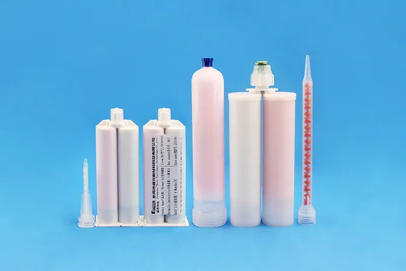
Figure 2. SHEEN thermal gel cartridges and dispensing accessories.
The two-part route: SE800AB. 8.0 ± 0.8 W/m·K. Cured hardness Shore 00 45–65. Full cure at 25 °C listed as ≥ 2 hours. Curing gives you another path to shape retention — and it brings its own homework: mix ratio, mixing uniformity, degree of cure. What we won’t do is hand you a datasheet and let you read “cured” as anti-creep, zero-stress, or easy rework. Those are test results, not adjectives.
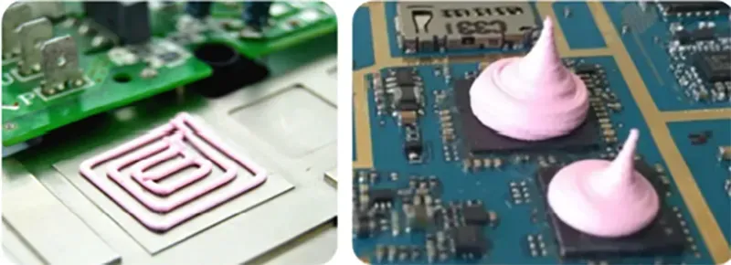
Figure 3. SHEEN dispensing in action — real shot patterns on real boards.
One Structure, One Validation Path
Use the incumbent material as the control. Same heat source, same heatsink, same gaps, same cooling. Then walk the candidate through four gates — exact conditions and pass thresholds are your project’s call:
- Gate 1 — dispensing and compression. Weigh single dots continuously; compare a fresh syringe, a post-shutdown restart, and different storage stages. Watch stringing, tailing, spread, and overflow into keep-out areas. Two-part adds mixing and cure-state checks.
- Gate 2 — initial thermal. Fixed power, stable environment, record device temperature plus the matching heatsink or housing temperature. Keep measurement points and cooling identical. If you back out results from delta-T and power, state the heat path and measurement boundary explicitly.
- Gate 3 — interface retention. Run the project’s thermal cycling, aging, or vibration profile; re-measure temperature rise at defined checkpoints. Log coverage area, edge movement, voids, and oil traces with one consistent method. Teardown disturbs the interface — use matched samples for comparison. And remember: an operating temperature range is not a reliability report.
- Gate 4 — rework. Record removal force, residue cleanup, and component condition; re-dispense and re-test temperature rise. Soft is not zero stress. Removable is not reusable.
What to Request in Round One
| First-round candidate | When to include it | What the sample must answer |
|---|---|---|
| SE60 (one-part) | Establish the 6 W/m·K baseline for gap filling and dispensing | Can current equipment dispense it stably? Does temperature rise meet spec at the real gaps? |
| SE120 (one-part) | Compare the real payoff of a higher conductivity grade | Is the temperature-rise benefit worth it? Are dispense parameters and bondline controllable? |
| SE800AB (two-part) | Structure and process allow curing; you want post-cure shape retention | Can mixing and curing run stably? Are the aged interface and rework acceptable? |
Engineering first-pass suggestions — final model count and sample quantities get confirmed per project.
The SE family layout, for further screening by thermal design and process needs:
| Family | Models | Nominal conductivity, W/m·K |
|---|---|---|
| One-part | SE20 / SE30 / SE40 / SE50 | 2 / 3 / 4 / 5 |
| One-part | SE60 / SE80 / SE100 / SE120 | 6 / 8 / 10 / 12 |
| Two-part | SE200AB / SE300AB / SE400AB | 2 / 3 / 4 |
| Two-part | SE500AB / SE600AB / SE800AB | 5 / 6 / 8 |
【Request a Custom Quote】When contacting our team, ask for the matching datasheet version, the feeding and storage instructions, and the actual test data available for bleed, temperature control, or rework questions — and double-check the test conditions behind each. Published parameters are screening material; what a specific model does on your target hardware still needs proving.
Source note: Product names, TDS values, comparison conditions, and limitations in this article are based on the supplied source document.
Sheen Thermal
Dongguan Sheen Electronic Technology Co., Ltd · Founded in 2008
Manufacturer of thermal interface materials and silicone foam for automotive electronics, energy storage, power electronics, communications and consumer electronics.
Certified
- ISO 9001:2015
- ISO 14001:2015
- IATF 16949:2016
What we supply
- Thermal conductivity Up to 90 W/m·K
- Thickness 0.3–10.0 mm
- Custom & samples Die-cut to drawing, 3–7 days
LAST:Nothing