
 English
 usheenthermal

Preparing Thermal Designs for Emerging 3.2T Optical Transceivers
Date:2026-09-10
3.2T is the next step beyond 1.6T, built on 400G-per-lane signalling, and it is still emerging: form factors and thermal envelopes are being worked out at the MSA level while IEEE standards work progresses lane rates behind it. For thermal design the practical consequence is that the enclosure assumptions from 1.6T carry forward — pluggable modules remain air-cooled through the housing and cage, while the co-packaged route moves the optics onto liquid-cooled silicon. The two architectures put completely different demands on the interface materials.
Within either architecture, the physics trend is familiar from the 800G-to-1.6T transition: absolute dissipation rises faster than the envelope grows, so local heat flux at the DSP and the optical engine sets the design problem. The interfaces the flux must cross — die to lid, lid to housing, housing to heatsink — are where the margin is won or lost.
Sheen Technology manufactures thermal interface materials — vertically aligned graphene and carbon fiber pads, boron nitride insulating pads, phase-change films, gap fillers and gels — and supports material-to-drawing matching.
Key Points: 3.2T Optical Transceivers Thermal Designs
➔ Hotspot Management: Employ graphite sheets, TIMs, and aluminum spreaders to flatten steep gradients on silicon photonics dies.
➔ Interface Optimization: Use gold-tin solder preforms and ultrathin TIM layers under hermetic lids to slash thermal impedance.
➔ Substrate Conductivity: Integrate copper-clad laminates, thermal vias, and heat sinks to offset Rogers material’s limited lateral heat spread.
➔ Advanced Cooling: Balance vapor chamber thickness, wick performance, and PCM cycling resilience for compact, high-flux modules.
Request the 3.2T Interface Material Planning Guide →
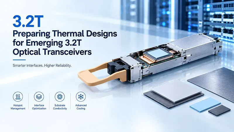
Note: This diagram was created with AI assistance and is not an actual photograph; the illustrated structure and operational logic align with real-world engineering applications and serve as a valid reference.
5 Fiery Challenges In 3.2T Optical Transceiver Thermal Designs
3.2T Optical Transceivers Thermal Designs pack serious power into tiny spaces, so cooling gets tricky fast. From silicon photonics hotspots to aging interface materials, each path matters. Sheen Technology approaches 3.2T thermal design by matching materials, interfaces, and cooling hardware to real operating loads.
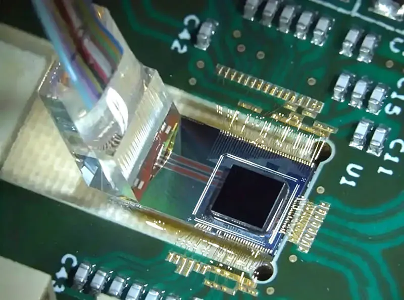
Uneven hotspot management on Silicon Photonics Die
Silicon Photonics can place laser, driver, and DSP loads close together, producing a sharp hotspot, high heat flux density, and uneven temperature gradient.
Heat control
- Graphite Sheet improves lateral thermal management.
- Thin Thermal Interface Material supports the cooling strategy without disturbing optical alignment.
Mechanical control
- Aluminum Heat Spreader and reliable die attach reduce local stress.
That balance is central to 3.2T Optical Transceivers Thermal Designs.
Hermetic Lid thermal impedance under high flux
A hermetic lid protects sensitive optics, but under high heat flux, every interface counts.
- Control lid thickness to shorten the conduction path.
- Keep Thermal Interface Material thin and uniform.
- Cut thermal resistance using Gold Tin Solder Preform joints.
- Lower thermal impedance supports faster heat dissipation.
For 3.2T optical transceivers, tiny interface gains add up quickly.
Limited heat spread on Rogers Material substrates
Rogers material gives the substrate strong electrical behavior for high-speed links, yet modest thermal conductivity can restrict heat spreading.
Copper Clad Laminate adds lateral conduction.
- Thermal vias move heat through the dielectric layer.
- Copper Heat Sink coupling gives the high-frequency laminate a stronger exit path.
Better thermal performance keeps 3.2T Optical Transceivers Thermal Designs from running into a hot wall.
Vapor Chamber integration hurdles in compact modules
A thin vapor chamber offers strong two-phase cooling, but module integration is no piece of cake.
Package fit
- The tight form factor limits chamber thickness and contact pressure.
Internal behavior
- Wick structure affects liquid return.
- Fluid dynamics govern evaporation and condensation.
Good thermal transport requires both mechanical fit and stable vapor-chamber operation in 3.2T Optical Transceivers Thermal Designs.
Phase Change Material cycling fatigue at 320 W/cm²
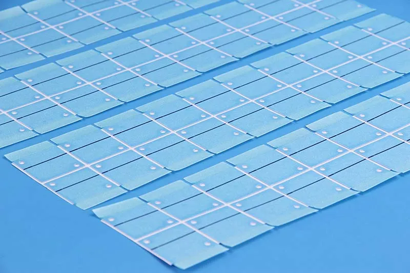
At 320 W/cm² high heat flux, Phase Change Material absorbs energy through latent heat, yet repeated melting creates tough thermal cycling conditions.
Track material movement.
- Expansion can cause pump-out from the interface.
Test repeated cycles.
- Fatigue may weaken contact and raise temperatures.
Validate long-term reliability.
- Dry-out and volume change deserve close attention.
For 3.2T transceiver cooling, cycle life matters as much as peak performance.
Bulleted Guide: 4 Factors Affecting Thermal Resistance
Good 3.2T optical transceiver thermal designs depend on more than picking a capable cooler. Heat must cross several interfaces before leaving the optical engine, and small details can add up fast. In practical 3.2T thermal design work, four factors deserve close attention. Get these right, and 3.2T optical transceiver thermal designs gain steadier heat flow without piling on needless complexity.
Thermal Interface Material thickness and contact pressure
Tune the interface around two linked variables:
- Keep bond line thickness low enough to cut thermal resistance, since extra material extends the heat path.
- Apply balanced compressive force so material compliance fills surface gaps.
Watch the limits:
- Excess pressure encourages pump-out and interface voiding.
- High thermal conductivity helps, but cannot rescue a poorly controlled bond line.
For 3.2T Optical Transceivers Thermal Designs, that balance also protects sensitive silicon photonics dies from unwanted mechanical loading.
Conductive paths through Copper Clad Laminate vs. Rogers Material
Copper Clad Laminate can spread heat effectively when designers put enough copper weight near hot components.
- Route heat into a copper plane and nearby thermal via arrays.
- Carry it through the Multilayer Circuit Board toward the heat sink.
- With Rogers Material, account for substrate material conductivity alongside dielectric constant and signal integrity needs.
That keeps heat dissipation practical instead of relying on dielectric-heavy paths.
Die Attach Film cure quality and void minimization
Control temperature and pressure.
- Proper polymerization stabilizes the adhesive layer.
- Suitable cure conditions support shear strength.
Inspect the finished bond.
- Low void percentage improves thermal conductivity.
- Uniform contact reduces local thermal stress.
In 3.2T Optical Transceivers Thermal Designs, tiny trapped air pockets are a big deal because concentrated heat can expose weak attachment areas quickly.
Micro Channel Cooler flow channel geometry
Micro Channel Cooler performance comes down to fluid dynamics and sensible geometry.
- Narrower channels can raise coolant velocity and the heat transfer coefficient, but also increase pressure drop.
- Channel depth, pitch, manifold balance, and fin thickness should distribute coolant evenly.
- Carefully managed turbulent flow can strengthen heat transfer without creating an impractical pumping burden.
For 3.2T Optical Transceivers Thermal Designs, uniform flow helps suppress optical-engine hotspots rather than merely cooling the easiest paths.
Comparing Thermal Gap Fillers: Silicone Vs. Graphite
3.2T Optical Transceivers Thermal Designs put a lot of heat into very little space, so interface material choice matters. Silicone fills imperfect gaps, while graphite moves concentrated heat across a wider area. For 3.2T Optical Transceivers Thermal Designs, the practical call comes down to gap geometry, pressure, insulation, and heat-flow direction.
Silicone
Silicone gap fillers are forgiving when optical transceiver parts do not line up perfectly. High Conformability helps the material follow tolerance changes and rough surfaces, cutting contact resistance without demanding extreme assembly pressure.

Mechanical fit
- Silicone elastomer pads can bridge changing gaps while protecting sensitive parts.
- Compression deflection matters: too stiff can load the PCB or optics; too soft can reduce dimensional control.
Thermal and electrical needs
- Higher Thermal conductivity can improve 3.2T thermal designs, but interface contact still counts.
- Dielectric strength is useful where electrical isolation is needed.
Gel behavior
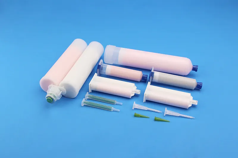
- Viscosity controls dispensing and flow. Silver-filled silicone or thermally conductive gel also needs checks for pump-out, cure behavior, and aging.
In short, silicone is a handy choice for messy tolerances, provided long-term compression and material movement are tested.
Graphite
Graphite takes a different route: it spreads a hotspot sideways instead of mainly filling a thick gap. That makes a thin Thermal sheet useful around dense 3.2T optical transceiver heat sources.
- Check heat direction. Anisotropic thermal conduction means In-plane conductivity can greatly exceed through-thickness conductivity.
- Use its Flexibility to maintain close contact across thin packaging spaces; good contact supports Low thermal resistance.
- Handle electrical risks carefully. Natural graphite conducts electricity, so edges and nearby components may require isolation.
| Material | Strong Direction | Electrically | Best Fit at 3.2T |
| Graphite spreading film | In-plane | Conductive | Lateral hotspot spreading on the die or lid; never the sole interface |
| Vertically aligned graphene pad | Through-plane | Conductive | High flux plus coplanarity error at TIM2 |
| Boron nitride pad | Through-plane | Insulating | Interfaces above live circuitry or power rails |
| Phase-change film | Through-plane | Filler-dependent | Flat clamped joints; thinnest bond line |
| Silicone gap pad / gel | Through-plane | Filler-dependent | Uneven heights under a common heatsink |
| Die-attach film (TIM1) | Through-plane | Filler-dependent | Package level — packaging house process |
| AuSn preform (TIM1) | Through-plane | Conductive | Package level — packaging house process |
*Typical roles for each material class; datasheets and application testing govern.
For 3.2T Optical Transceivers Thermal Designs, graphite fits heat-spreading jobs well, while silicone remains stronger at filling uneven physical gaps.
Scenario: Data Center Racks—Optimizing 3.2T Thermal Flow
High-density racks make 3.2T Optical Transceivers Thermal Designs a rack-wide cooling job, not just a module issue. Air paths, conductive hardware, and temporary heat storage must work together. Sheen Technology approaches 3.2T optical thermal design with practical control of heat from slot to aisle.
Rack-level airflow mapping with Vapor Chamber modules
Good airflow mapping shows where hot exhaust circles back through a data center rack and raises module inlet temperatures.
Map operating conditions:
- Check temperature gradient patterns from lower to upper slots.
- Trace bypass and recirculation around dense 3.2T optical transceivers.
Match hardware to airflow:
- Align each Vapor Chamber with the main air path.
- Position fins so thermal flow meets less resistance while maintaining strong heat dissipation.
That coordination keeps cooling performance predictable as traffic ramps up.
Deploying Copper Heat Sink arrays for consistent cooling
A Copper Heat Sink moves heat quickly because copper offers high thermal conductivity. Still, just adding metal won’t cut it.
- Size the cooling array around transceiver spacing and fan capacity.
- Tune fin design so pressure drop does not choke rack airflow.
- Apply even mounting force and a suitable thermal interface material.
These choices improve transceiver thermal control, heat dissipation, and temperature stabilization, supporting 3.2T Optical Transceivers Thermal Designs under sustained loads.
Embedding Phase Change Material pads in server slots
A Phase Change Material pad uses latent heat to absorb brief temperature spikes.
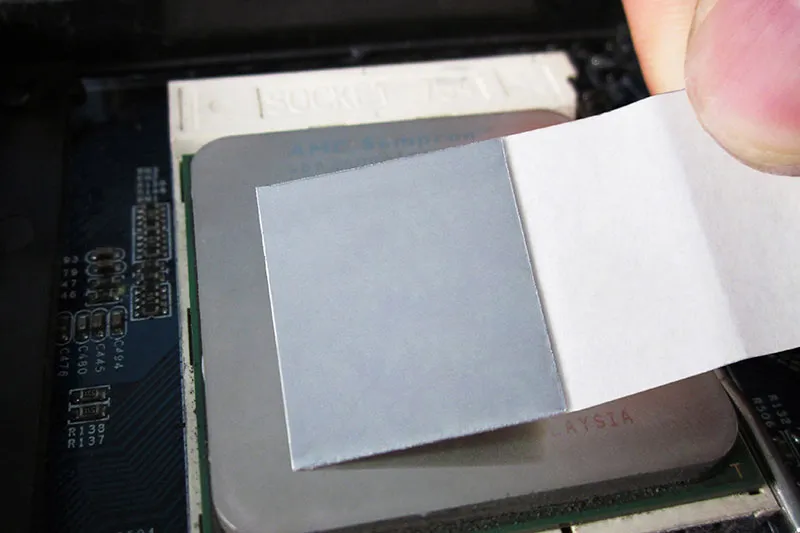
For slot integration:
- Place each thermal pad near a high-load server slot.
- Keep the thermal interface thin and well contacted.
For repeat use:
- Select a melt range suited to normal temperature regulation.
- Confirm regeneration time and containment after heat absorption cycles.
PCM complements airflow rather than replacing it, giving 3.2T transceiver cooling extra breathing room during short bursts.
Send Us Your 3.2T Package Drawing for TIM2 Matching →
Internal Linking
- 800G to 1.6T: What Changes in Optical Module Thermal Design
- Thermal Management for 1.6T Optical Transceivers: Key Design Challenges
- How Graphene Thermal Pads Optimize 1.6T Optical Transceiver Cooling
- Vertically Aligned Graphene Thermal Pad vs. Silicone: Which Wins
- Analyzing Thermal Pad Thermal Cycling Reliability Under Stress
Sheen Thermal
Dongguan Sheen Electronic Technology Co., Ltd · Founded in 2008
Manufacturer of thermal interface materials and silicone foam for automotive electronics, energy storage, power electronics, communications and consumer electronics.
Certified
- ISO 9001:2015
- ISO 14001:2015
- IATF 16949:2016
What we supply
- Thermal conductivity Up to 90 W/m·K
- Thickness 0.3–10.0 mm
- Custom & samples Die-cut to drawing, 3–7 days